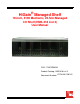
HiGain® Managed Shelf 19-inch, 3190 Mechanic, 22-Slot Managed CO Shelf (HMS-318 List 3) User Manual CLEI: T1MF2S04RA Product Catalog: HMS-318 List 3 Document Number: LTPH-UM-1261-01
REVISION HISTORY The Revision History provides a summary of any changes in this manual. Please make sure you are using the latest revision of this manual. December 20, 2004 Revision 01 Release Date December 20, 2004 Revisions Made Initial Release This manual is available online at ADC’s website (www.adc.com/documentationlibrary/) or you can order copies of the manual by contacting your sales representative. Please ask for document LTPH-UM-1261-01. Copyright ©2004 ADC Telecommunications, Inc.
Table of Contents About This Manual ..........................................................................................................ix Introduction ...............................................................................................................................ix Audience ...................................................................................................................................ix Related Publications ............................................................
Table of Contents iv December 20, 2004 LTPH-UM-1261-01
List of Figures Figure 1-1. HMS-318 List 3 Shelf - Front View ................................................................... 1-2 Figure 1-2. HMS-318 List 3 Shelf - Rear View .................................................................... 1-3 Figure 1-3. Input Power Terminal Block (TB1) .................................................................... 1-5 Figure 1-4. Alarms Wire-Wrap Field (TB2) ......................................................................... 1-6 Figure 1-5.
List of Figures vi December 20, 2004 LTPH-UM-1261-01
List of Tables Table 1-1. HMS-318 List 3 Shelf Rear-Panel Connections (LPS-300C) .............................. 1-4 Table 1-2. Alarms Wire-wrap Field Functional Description .................................................. 1-7 Table 1-3. J26 – RS-232/X.25 Management Port (DTE) ................................................... 1-12 Table 1-4. J27 – AUX RS-232 Management Port (DTE) ................................................... 1-13 Table 2-1. HMS-318 List 3 Shelf Parts List ..........................
List of Tables viii December 20, 2004 LTPH-UM-1261-01
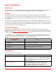
ABOUT THIS MANUAL INTRODUCTION This manual provides essential information about the HiGain® Management Shelf (HMS-318 List 3) along with stepby-step instructions on how to install the shelf into a Central Office (CO) or telco-style equipment rack. AUDIENCE This manual is written for people who install and plan the installation of ADC products in a Central Office environment.
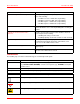
About This Manual December 20, 2004 Chapter Appendix A: Signal and Pin Assignments Description Lists Tip and Ring signal and pin assignments to the HMS-318 List 3 shelf, including: • P1-DSX-1 Receive or xDSL B IN, Tip and Ring • P2-DSX-1 Transmit or xDSL A IN, Tip and Ring • P3-HDSL Span 1 or xDSL A OUT, Tip and Ring • P4-HDSL Span 2 or xDSL B OUT, Tip and Ring Appendix B: Standard PIC Color Code Lists the standard PIC color codes with the Pair Number crossreferenced with the colors of the Tip and Ring
December 20, 2004 About This Manual Reader Alert CAUTION WARNING DANGER Meaning Alerts you to possible data loss, service-affecting procedures, or other similar type problems Alerts you that failure to take or avoid a specific action might result in hardware damage or loss of service Alerts you that failure to take or avoid a specific action might result in personal harm EU COMPLIANCE The product complies with the requirements of the Low Voltage Directive 73/23/EEC, EMC Directive 89/336/EEC, and the R
About This Manual DANGER December 20, 2004 To prevent electrical shock, be careful when working near HDSL loops and telecommunications circuits. Coming in contact with high electrical potential will result in death or severe personal injury. IMPORTANT ! DANGER DANGER ATTENTION The shelf chassis must be properly grounded to ensure personal and equipment safety. To prevent electrical shock, never install telco equipment in a wet location or during a lightning storm.
Chapter 1 PRODUCT DESCRIPTION The HMS-318 L3 is a 22-slot, 3190 mechanics shelf that is capable of being managed locally or remotely. It can be mounted in a 19-inch rack and is fully NEBS 3 and UL-60950 complaint. The ADC HiGain® Management Shelf (HMS-318 List 3) weighs approximately 17 pounds (7.7 kg). It measures 17.3 in. wide x 5.22 in. high x 12 in. deep (43.9 cm x 13.3 cm x 30.5 cm). These dimensions do not include the mounting brackets that are factory-installed to the shelf.
Chapter 1: Product Description December 20, 2004 TYPICAL HMS-318 LIST 3 SHELF APPLICATIONS Capable of using various components in different types of applications, the HMS-318 List 3 shelf is designed as a very adaptable shelf.
December 20, 2004 Chapter 1: Product Description HMS-318 List 3 Rear View The HMS-318 List 3 shelf input power, 5-position terminal block (labeled TB1) and the alarms (labeled Alarms) wirewrap connections are located on the rear panel (see Figure 1-2). The Bonding (Safety ground) is located on the upper right corner extension of the right panel. The label (BONDING WIRE MIN #10 AWG) is located on the right corner of the rear panel (see Grounding Lug and Hexhead Screw, Figure 1-2).
Chapter 1: Product Description December 20, 2004 Table 1-1. HMS-318 List 3 Shelf Rear-Panel Connections (LPS-300C) Connector/Terminal Block Connector Type Connectory Label Description J24 BNC-T (Female) 10 BASE-2 10BASE-2 Management Port J25 RJ-45 10 BASE-T 10BASE-T Management Port J26 RS-232 DB-25 (Female) OS RS232 DTE PORT RS-232/X.
December 20, 2004 Chapter 1: Product Description POWER AND ALARM CONNECTIONS The HMS-318 List 3 shelf has a separate split input power (TB1) and an Alarms wire-wrap field (TB2). The following paragraphs provide information about TB1 and TB2.
Chapter 1: Product Description December 20, 2004 Alarms Wire-Wrap Field IMPORTANT ! Before making power connections (CO primary power feeds A and B) to the HMS-318 List 3 shelf, ensure that the Main CO power breaker is off. Otherwise, severe injury to the installer or damage to the unit may result. Terminate the alarm leads from the CO alarm system to the HMS-318 List 3 shelf.
December 20, 2004 Chapter 1: Product Description In the HMU/HLU configuration, for example, for detailed information about the different types of alarms, refer to the “Managing Alarms” section in the HMU-319, H2TU-C-319, or H4TU-C-319 User Manuals. Specifically, the manual describes the types of alarms the HMU-319 reports, when the alarm occurs, and how to respond to the alarm using the ACO. Table 1-2.
Chapter 1: Product Description December 20, 2004 CONNECTING TO HDSL, HDSL2, AND HDSL4 CIRCUITS The following paragraphs provide information on making DSX-1 and HDSL, HDSL2, and HDSL4 connections to the HMS-318 List 3 shelf. Plug-in Connections DSX-1 and HDSL, HDSL 2, or HDSL4 DSX-1 connections to the HMS-318 List 3 shelf can be made through the HMS-318 List 3 shelf’s rear-panel 50-pin Amphenol-type male connectors P1, RCV to DSX (labeled CO PAIR 1) and P2, XMT from DSX (labeled CO PAIR 2).
December 20, 2004 Chapter 1: Product Description DSX-1 Tip (IN) A 1 DSX-1 Tip 1 (OUT) B 2 C 3 D 4 Error Alarm Bus E 5 HDSL Loop 1 - Tip F 6 System Alarm* H 7 Management Bus* Frame Ground J 8 -48 Vdc Battery HDSL Loop 2 - Tip K 9 HDSL Loop 2 - Ring FL (not used) L 10 DSX-1 Ring (OUT) Ground (GND) Fuse Alarm ** Notes: * Minor alarm output is normally floating (0 to -60V maximum) and a ground (10 ma maximum, +5 Vdc for HLU-319 List 2D) when activated ** Fuse alarm is normal
Chapter 1: Product Description December 20, 2004 DSX-1 Tip (IN) A 1 DSX-1 Ring (IN) DSX-1 Tip 1 (OUT) B 2 DSX-1 Ring 1 (OUT) C 3 D 4 E 5 Ground (GND) HDSL4 Loop 1 Tip F 6 HDSL4 Loop 1 Ring System Alarm * H 7 Management Bus * Frame Ground J 8 -48 Vdc Battery HDSL4 Loop 2 Tip K 9 HDSL4 Loop 2 Ring Factory use only L 10 Fuse Alarm ** Notes: * System alarm and management bus reserved.
December 20, 2004 Chapter 1: Product Description Wire Wrap Connections – Span Powered xDSL Figure 1-8 shows the LPS-300C slot pinouts on the HMS-318 List 3 shelf rear panel for xDSL circuits. xDSL A IN A 1 xDSL A IN xDSL B IN B 2 xDSL B IN C 3 D 4 E 5 F 6 H 7 Management Bus * Frame Ground J 8 -48 Vdc Battery xDSL B OUT K 9 L 10 xDSL A OUT Ground (GND) Fuse Alarm ** Notes: * System alarm and managem ent bus reserved.
Chapter 1: Product Description December 20, 2004 RS-232/X.25 REMOTE MANAGEMENT PORTS Two EIA RS-232 communications ports, J26 (labeled OS RS232 PORT) and J27 (labeled AUX RS232 PORT), located on the HMS-318 List 3 shelf rear panel (see Figure 1-9 on page 12), provide optional OS and AUX management interfaces for connection to a HiGain system.
December 20, 2004 Chapter 1: Product Description Table 1-4. J27 – AUX RS-232 Management Port (DTE) Pin No.
Chapter 1: Product Description December 20, 2004 Note: Refer to the respective ADC card user manuals to determine the maximum number of cards that can be installed in a shelf before exceeding the maximum heat dissipation density of the telco-style equipment rack configuration. Figure 1-11 shows a typical example of a CO equipment rack layout using HMS-318 List 3 shelves.
December 20, 2004 Chapter 1: Product Description AIR FLOW GUIDELINES To ensure adequate air flow through the telco-style equipment rack, it is recommended that you maintain a clearance of at least 6 inches (15.2 cm) in the front and the back of the rack at all times.
Chapter 1: Product Description 1-16 December 20, 2004 LTPH-UM-1261-01
Chapter 2 INSTALLATION This section provides specific information about preparing your site for installation. Included are specific preparatory information, safety guidelines, specific rack-mounting guidelines, adapter bracket mounting, rack mounting, DSX and HDSL or Span Powered xDSL connections, and power and alarm connections.
Chapter 2: Installation December 20, 2004 Unpacking and Checking the Contents of your Shipment The shipping package for the HMS-318 List 3 is designed to reduce the possibility of product damage associated with routine material handling experienced during shipment. To reduce the potential damage to the product, transport the shelf in its ADC-specified packaging. Failure to do so may result in damage to the shelf. Also do not remove the shelf from its shipping container until you are ready to install it.
December 20, 2004 Chapter 2: Installation Notes: Required Tools The following tools are required to install the shelf: • Grounding or ESD-preventive wrist strap • #2 Phillips-head screwdriver • #1 Phillips-head screwdriver • Straight-slot-head screwdriver • Cable preparation tools • A 5/16-inch open-end wrench • Tape measure • Wire strippers • An Amphenol crimping tool for making up connectors (if necessary). Note: All other tools are normally carried in a craftsman’s tool set.
Chapter 2: Installation December 20, 2004 SAFETY GUIDELINES The safety guidelines (see Chapter 1: “Safety Guidelines” on page 1-iv) are provided to help ensure your safety and to protect your equipment. The list on page iv may not identify all potentially hazardous situations in your working environment, so be alert and exercise good judgment at all times. MOUNTING THE HMS-318 LIST 3 SHELF Each HMS-318 List 3 shelf has a hardware kit.
December 20, 2004 Chapter 2: Installation Adapter Bracket Mounting Procedure (19-inch Telco-style Equipment Rack) Adapter bracket placement depends on the type of telco-style rack you plan to use to install the HMS-318 List 3 shelf. First, check the mounting adapter brackets on the shelf to determine whether the factory-installed configuration is correct for the planned telco-style equipment rack installation. The following procedure describes how to install the adapter brackets.
Chapter 2: Installation December 20, 2004 Step Action 1 Locate the mounting holes of the HMS-318 List 3 shelf for the desired rack width 23 inches (58.4 cm) and position (2- or 5-inch recess mounting). 2 Align each adapter bracket with the HMS-318 List 3 shelf and attach to the desired rack width 23 inches (58.4 cm) and position (2- or 5-inch recess mounting) with the #6-32 x .25 inch screws (provided). 3 Insert the screws (4 places) and tighten using a #2 Phillips screwdriver.
December 20, 2004 Chapter 2: Installation Rack Mounting Procedure To secure the HMS-318 List 3 shelf to the telco-style rack, you must use the mounting screws provided or follow your local practices for installing the shelves into your telco-style equipment rack.
Chapter 2: Installation December 20, 2004 DSX and HDSL Connector Procedure Step Action 1 Complete one of the following steps to make the DSX-1 and HDSLx connections to the shelf using one of the following methods: Plug the DSX-1 interface cables into P1 and P2 and the HDSLx interface cables into P3 and P4. Wire-wrap the DSX-1 and HDSLx inputs to the appropriate individual card slots. Pin assignments are listed in Appendix A: “Signal and Pin Assignments” on page A-1.
December 20, 2004 Chapter 2: Installation BONDING (SAFETY) GROUND, POWER AND FRAME GROUND, ALARM, AND OPTIONAL FAN INPUTS IMPORTANT ! Before making connections to the HMS-318 List 3 shelf, ensure that the Main CO power breaker is off. Otherwise, severe injury to the installer or damage to the unit may result.
Chapter 2: Installation December 20, 2004 Step Action 1 Looking at the HMS-318 List 3 rear panel, find the ground lug location (labeled BONDING WIRE MIN #10 AWG) on the upper right corner extension of the right panel (see Figure 2-1). 2 Measure between the telco-style rack and the HMS-318 List 3 Shelf the correct length of a #10 AWG (minimum) ground wire so that it reaches the ground lug location on the HMS-318 List 3 Shelf, and cut. Leave enough excess to allow for tying to the rack.
December 20, 2004 Chapter 2: Installation Power and Frame Ground Procedure IMPORTANT ! To avoid voltage differences from building up between the shelf ground (GND) bus and the ground pins of the management terminal that connects to the RS-232 ports, connect the shelf ground pins and the terminal ground bus to the TB1 FGND (frame ground) pin.
Chapter 2: Installation December 20, 2004 Optional Fan Alarm Procedure Note: The FAN terminals wire-wrap field provides access to the Normally Open (NO), Form A fan relay contact located on the HMU-319 management unit. A temperature monitor activates this fan relay when the shelf temperature exceeds 45°C (±1°C) and deactivates the relay when the temperature drops below 35°C (±1°C). If the temperature exceeds 77°C (±1°C) a critical alarm is also generated.
December 20, 2004 Chapter 2: Installation INSTALLING THE HMU-319 WITH HLU-319, H2TU-C-319, H4TU-C-319 Install the line units (HLUs) into slots 1 through 22 and the HMU-319 management unit into slot 23 of the HMS-318 List 3 shelf (see “HMS-318 List 3 Shelf - Front View” on page 1-2 for slot location). Install HMU and HLU Procedure ATTENTION Use anti-static wrist-straps connected to the ESD Jack (located on the right adapter bracket, see Figure 1 on page 3) when inserting a circuit card.
Chapter 2: Installation December 20, 2004 Install LPS-300C Procedure ATTENTION Use anti-static wrist-straps connected to the ESD Jack (located on the right adapter bracket, see Figure 1-1 on page 1-2) when inserting a circuit card. Avoid touching components on the circuit card. Step Action 1 Hold the LPS-300C Power Module vertically with the front of the circuit card toward you. Align the top and bottom edges of the LPS-300C with the HMS-318 List 3 shelf slot guides.
Appendix A SIGNAL AND PIN ASSIGNMENTS The Tip and Ring signal and pin assignments to the HMS-318 List 3 shelf are: • P1-DSX-1 Receive or xDSL B IN, Tip and Ring (see Table A-1) • P2-DSX-1 Transmit or xDSL A IN, Tip and Ring (see Table A-2 on page A-2) • P3-HDSL Span 1 or xDSL A OUT, Tip and Ring (see Table A-3 on page A-4) • P4-HDSL Span 2 or xDSL B OUT, Tip and Ring (see Table A-4 on page A-5) Connector P1 - DSX-1 Receive or Span Powered xDSL (xDSL B IN) Table A-1 provides signal and pin assignment informa
Appendix A: Signal and Pin Assignments Cable Pin Number December 20, 2004 Slot 14 40 Ring 15 15 41 16 17 18 19 20 Tip Ring 21 21 47 Tip Ring 20 46 Tip Ring 19 45 Tip Ring 18 44 Tip Ring 17 43 Tip Ring 16 42 Card Slot Pin Number Tip Ring 22 22 Tip Ring Connector P2 - DSX-1 Transmit or Span Powered xDSL (xDSL A IN) Table A-2 provides signal and pin assignment information for making DSX-1 transmit or Span Powered xDSL (xDSL A IN) circuit connections to the HMS-318 List 3 shelf.
December 20, 2004 Appendix A: Signal and Pin Assignments Cable Pin Number Slot 8 34 Ring 9 9 35 10 11 12 13 14 15 16 17 18 19 20 22 LTPH-UM-1261-01 Tip Ring 21 21 47 Tip Ring 20 46 Tip Ring 19 45 Tip Ring 18 44 Tip Ring 17 43 Tip Ring 16 42 Tip Ring 15 41 Tip Ring 14 40 Tip Ring 13 39 Tip Ring 12 38 Tip Ring 11 37 Tip Ring 10 36 Card Slot Pin Number Tip Ring 22 Tip Ring A-3
Appendix A: Signal and Pin Assignments December 20, 2004 Connector P3 - HDSL Span 1 (HDSL, HDSL2, or HDSL4) or Span Powered xDSL (xDSL A OUT) Table A-3 provides connector P3 signal and pin assignment information for making HDSL Span 1 (HDSL, HDSL2, or HDSL4) or Span Powered xDSL (xDSL A OUT) connections to the HMS-318 List 3 shelf. Table A-3.
December 20, 2004 Appendix A: Signal and Pin Assignments Cable Pin Number Slot 18 Card Slot Pin Number Ring 44 19 Tip 19 Ring 45 20 Tip 20 Ring 46 21 Tip 21 Ring 47 22 Tip 22 Ring Connector P4 - HDSL Span 2 (HDSL, HDSL2, or HDSL4) or Span Powered xDSL B OUT Table A-4 provides signal and pin assignment information for making HDSL Span 2 (HDSL, HDSL2, or HDSL4) or Span Powered xDSL (xDSL B OUT) connections to the HMS-318 List 3 shelf. Table A-4.
Appendix A: Signal and Pin Assignments December 20, 2004 Cable Pin Number Slot 12 38 Ring 13 13 39 14 15 16 17 18 19 20 22 A-6 Tip Ring 21 21 47 Tip Ring 20 46 Tip Ring 19 45 Tip Ring 18 44 Tip Ring 17 43 Tip Ring 16 42 Tip Ring 15 41 Tip Ring 14 40 Card Slot Pin Number Tip Ring 22 Tip Ring LTPH-UM-1261-01
Appendix B STANDARD PIC COLOR CODE This appendix lists the standard PIC color codes in tabular format with the Pair Number cross-referenced with the colors of the Tip and Ring wires used by the installer. Table B-1.
Appendix B: Standard PIC Color Code B-2 December 20, 2004 LTPH-UM-1261-01
Appendix C CIRCUIT CARD PREVENTIVE MEASURES This appendix describes the preventive measures that should be observed for the following: • Handling and storing of circuit cards. • Installing/replacing circuit cards sensitive to static electricity. HANDLING CIRCUIT CARDS Damage to circuit cards, particularly those that are sensitive to static electricity, may occur at any time. Follow these safeguards when handling circuit cards. • Avoid dropping a circuit card.
Appendix C: Circuit Card Preventive Measures December 20, 2004 Circuit Card Ejector Tab or Built-in Thumb Hold Most circuit cards have an ejector tab that is used to assist the installer in inserting and removing each circuit card. These ejector tabs are typically located at either the top or bottom of the circuit card. Other types of circuit cards have a built-in thumb hold for gripping the card. Follow the procedure given to remove and insert a circuit card.
Appendix D SPECIFICATIONS Power Requirements CO Battery Voltage -48 Vdc nominal (-42.5 Vdc to -56.5 Vdc) Fuse Maximum 15 Aa Compliance NEBS GR-63-CORE, Issue 2 GR-1089-CORE, Issue 3 SR-3580, Level 3 Safety UL/cUL 60950-1 UL/cUL 60950-21 EN 60950-1:2001 EN 60950-21:2003 EMC EN 300 386-2 V1.1.3:December 1997 Physical Dimensions (HxWxD) 5.22 in. x 19 in. x 12 in. (13.3 cm x 48.3 cm x 30.5 cm), without mounting brackets Weight 17 lb. (7.
Appendix D: Specifications December 20, 2004 Accessories Supplied Brackets (attached at factory) for mounting in either 19-inch (48.3 cm) or 23-inch (58.4 cm) bays Brackets for mounting in ETSI rack Accessories Available Extender Bracket Kit: available in three colors: EB-52, gray; EB-52B, black; EB-52P, putty). a.If fuse size and wire gauge requirements are not specific, follow local practices for determining your fuse and wire gauge size.
Appendix E PRODUCT SUPPORT ADC Customer Service Group provides expert pre-sales support and training for all of its products. Technical support is available 24 hours a day, 7 days a week by contacting the ADC Technical Assistance Center. Sales Assistance: 800.366.3891 Quotation Proposals, Ordering and Delivery General, and Product Information Systems Integration: 800.366.
Appendix E: Product Support E-2 December 20, 2004 LTPH-UM-1261-01
GLOSSARY A ACO – Alarm Cutoff AUD – Audible (alarm) AUX – Auxiliary port AWG – American Wire Gauge C CLEI – Common Language Equipment Interface CO – Central Office COM – Common CRIT – Critical (alarm) D DSL – Digital Subscriber Loop DSX-1 – DS-1 Cross-connect frame E E1 – 2.
Glossary December 20, 2004 O OS port – Operator Services port P PIC – Plastic Insulated Conductor R RCV – Receive RMA – Return Material Authorization RX – Receive S SYS ID – System Identifier (alarm) T T1 – 1.
Certification and Warranty FCC Class A Compliance This equipment has been tested and found to comply with the limits for a Class A digital device, pursuant to Part 15 of the FCC Rules. These limits are designed to provide reasonable protection against harmful interference when the equipment is operated in a commercial environment.
World Headquarters ADC Telecommunications, Inc. PO Box 1101 Minneapolis, MN 55440-1101 USA For Technical Assistance Tel: 800.366.