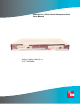
HRM-238 List 1 HiGain Retrofit Management Shelf User Manual Product Catalog: HRM-238 L1 CLEI: T1MFW004
LTPH-UM-1237-04 Revision History To order copies of this manual, use document catalog number LTPH-UM-1237-04. (Copies of this publication can be downloaded from the ADC website at www.adc.com. To order a hard copy, please contact your sales representative.) Issue Release Date Revisions Made 1 May 9, 2003 Initial release 2 March 31, 2004 Updated Certificate and Warranty and Product Support Sections. 3 April 28, 2004 Misc technical updates 4 July 21, 2004 Misc technical updates/additions.
LTPH-UM-1237-04 Using This Manual USING THIS MANUAL The following conventions are used in this manual where applicable: • Monospace type indicates screen text. • Keys you press are indicated by small icons such as Y or ENTER . Key combinations to be pressed simultaneously are indicated with a plus sign as follows: CTRL + ESC . • Items you select are in bold. The following types of messages, identified by icons, may appear in text. Notes provide information about special circumstances.
Inspecting Shipment iv LTPH-UM-1237-04 July 21, 2004 HRM-238 List 1
LTPH-UM-1237-04 Table of Contents TABLE OF CONTENTS Overview ____________________________________________________________________________ 1 Features ..............................................................................................................................................1 Operational Capabilities.....................................................................................................................2 Application ..............................................................
List of Figures LTPH-UM-1237-04 LIST OF FIGURES 1. HRM-238 List 1 (front view) ........................................................................................................................ 1 2. Recommended Network Setup for 220 Type Shelves................................................................................... 2 3. Recommended Network Setup for 3190 Type Shelves................................................................................. 3 4.
LTPH-UM-1237-04 List of Tables LIST OF TABLES 1. HRM-238 Connectors ......................................................................................................................................4 2. Terminal Block (TB1) ......................................................................................................................................6 3. P1 and P6 NMA Connectors ......................................................................................................................
List of Tables viii LTPH-UM-1237-04 July 21, 2004 HRM-238 List 1
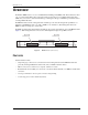
LTPH-UM-1237-04 Overview OVERVIEW The HiGain® HRM-238 List 1 is a two-slot HiGain Retrofit Management (HRM) shelf. This shelf fits into either a 19- or 23-inch Central Office (CO) equipment rack. It accommodates up to two HiGain management units (HMU-319s). It is used in conjunction with 220-type, unmanaged 3190 type, and DDM+ type mechanic shelves to manage HiGain line units.
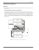
Overview LTPH-UM-1237-04 OPERATIONAL CAPABILITIES Application With two HMU-319 management units installed, the HRM-238 shelf provides network management for up to 56 HiGain line units. Recommended Network Setup for 220 Type Shelves The configuration shown in Figure 2 is the recommended setup for 220 type mechanics shelves. Position the HRM-238 shelf between the 220 type shelves, with up to two 220-type shelves above and two below.
LTPH-UM-1237-04 Overview Recommended Network Setup for 3190 Type Shelves The configuration shown in Figure 3 is the recommended setup for 3190 type mechanics shelves. Position the HRM-238 shelf below the 3190 type shelves. This limits the distance for the wire leads between the connectors for the management units and the line units they manage. Figure 3 shows the HRM-238 shelf from the rear view with the A-side connectors on the right and the B-side connectors on the left.
Overview LTPH-UM-1237-04 Management Cabling Figure 5 shows the location for each connector on the HRM-238 shelf backplane. Table 1 lists the shelf connector types and management functions available to the HMU-319 management units through those connectors.
LTPH-UM-1237-04 Installation INSTALLATION INSPECTING YOUR SHIPMENT Upon receipt of the equipment: • Unpack each container and inspect the contents for signs of damage. If the equipment has been damaged in transit, immediately report the extent of damage to the transportation company and to ADC Telecommunications, Inc. Order replacement equipment, if necessary. • Check the packing list to ensure complete and accurate shipment of each listed item.
Installation LTPH-UM-1237-04 Table 2. Terminal Block (TB1) Terminal Description 1 -48V_A 2 -48V_B 3 BATTERY RETURN 4 FGND 1 Remove the fuse(s) in the equipment bay fuse panel for the circuit(s) where the HRM-238 shelf battery wire(s) will terminate. 2 Connect one end of the frame ground wire to Terminal 4 (FGND) on TB1 of the HRM-238 shelf and attach the other end of the frame ground wire to the CO ground wire termination point.
LTPH-UM-1237-04 Installation Connect NMA Wiring From the 50-pin Amphenol connector P1 and/or P6 (Figure 8), wire directly to the NMA pin 46 on the 220-type shelf backplane for each line unit being managed. Route wires from the P1 and P6 connectors to the NMA 220-type mechanics shelves as shown in Figure 2 on page 2. Refer to Table 3 for P1 and P6 NMA connector information. 50-pin Amphenol connector (P6) 50-pin Amphenol connector (P1) H0548-A Figure 8.
Installation LTPH-UM-1237-04 Table 3.
LTPH-UM-1237-04 Installation Connect to a LAN or Interconnect Shelves Use the BNC connector (Figure 9) when required for access using a LAN or for interconnecting multiple shelves. Consult the appropriate user manual for the HMU-319 management unit and for the software used in the application. See Table 4 for information on BNC connector J1 and J3. H0549-A BNC connector (J3) BNC connector (J1) Figure 9. Table 4.
Installation LTPH-UM-1237-04 Use a null modem connector for cross-over cabling when attaching a device that is not configured as DCE (such as terminals or computers running terminal emulation software) to these connectors. Table 5 shows the pinouts for the two AUX ports (one port for each management unit). Table 6 shows the pinouts for the two OS ports (one port for each management unit). Table 5.
LTPH-UM-1237-04 Installation IDENTIFYING ALARMS Alarm relay contacts for each management unit are on J13 and J14 (Figure 11). Install wiring between these pins and an alarm monitoring device per local practice. Table 7 describes the alarm J13 and J14 pinouts. H0651-A Alarm relay pins (J14) Alarm relay pins (J13) Figure 11. Table 7.
Installation LTPH-UM-1237-04 Verify Cabling Verify the following: 1 2 Verify a minimum of -42 Vdc and a maximum of -56 Vdc between the following: a -48 Vdc battery screw Terminal 1 and the battery common Terminal 3 (BATTERY RETURN) b -48 Vdc battery screw Terminal 2 (when used) and the battery common Terminal 3 (BATTERY RETURN) Visually verify that all connections are securely terminated.
LTPH-UM-1237-04 Appendix A - Specifications APPENDIX A - SPECIFICATIONS Power Maximum power 10.0 Watts CO Supply -48 Vdc nominal (-42.5 Vdc to -56.5 Vdc) Fuse Size 0.5A Physical Material Steel Finish Zinc plated Capacity 2 management modules (HMU-319 or MMU-319) Mounting 19- or 23-inch rack Dimensions Height 1.75 in. (4.39 cm) Width 17 in. (43.18 cm), without mounting brackets 18.37 in. (46.65 cm), mounting brackets set for 19-inch rack 22.37 in. (56.
Appendix B - Product Support LTPH-UM-1237-04 APPENDIX B - PRODUCT SUPPORT ADC Customer Service Group provides expert pre-sales and post-sales support and training for all its products. Technical support is available 24 hours a day, 7 days a week by contacting the ADC Technical Assistance Center. Sales Assistance 800.366.3891 • Quotation Proposals • Ordering and Delivery • General Product Information Systems Integration 800.366.
LTPH-UM-1237-04 Appendix C - Abbreviations APPENDIX C - ABBREVIATIONS B BNC: Bayonet-Lockingl Connector C CO: Central Office D DCE: Data Communication Equipment DTE: Data Terminal Equipment H HCS: HiGain Card Shelf HMU: HiGain Management Unit HRM: HiGain Retrofit Management L LAN: Local Area Network N NMA: Network Management Agent P PADs: Packet Assembler/Disassemblers HRM-238 List 1 July 21, 2004 15
Appendix C - Abbreviations 16 LTPH-UM-1237-04 July 21, 2004 HRM-238 List 1
CERTIFICATION AND WARRANTY FCC COMPLIANCE This equipment does not have any clocking source, and is deemed to be a passive device per FCC guidelines. When used in conjunction with any clocking devices, this combined system may radiate radio frequency energy that can cause harmful interference to radio communications. Operation of such a system in a residential area is likely to cause harmful interference, in which case the user will be required to correct the interference at his own.
World Headquarters ADC Telecommunications, Inc. PO Box 1101 Minneapolis, Minnesota USA 55440-1101 Technical Assistance Tel: 800.366.