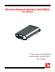
Ethernet Network Interface Unit (ENIU) User Manual 20383-A1 ENIEG X XEG XX1B Product Catalog: ENI-EGXXEGXX1B Document Number: AIWN-UM-7001-01 CLEI: IPUIAY5F~~
REVISION HISTORY The Revision History provides a summary of any changes in this manual. Please make sure you are using the latest revision of this manual. August 7, 2006 Revision 01 Release Date August 7, 2006 Revisions Made Initial release with new format. Replaces ADCP-92-061 (Issue 1) (1315502). This manual is available online at ADC’s website (www.adc.com/documentationlibrary/) or you can order copies of the manual by contacting your sales representative. Please ask for document AIWN-UM-7001-01.
Table of Contents Chapter 1: Overview ....................................................................................................... 1-1 Product Description .................................................................................................................. 1-1 Front Panel ............................................................................................................................... 1-2 Chapter 2: Installation ..........................................................
Table of Contents iv August 7, 2006 AIWN-UM-7001-01
List of Figures Figure 1-1. Figure 1-2. Figure 2-1. Figure 2-2. Figure 2-3. Figure 2-4. Figure 2-5. Figure 2-6. ENIU with SFPs ................................................................................................ 1-1 ENIU Front View ............................................................................................... 1-2 Inserting ENIU into Mounting Bracket .............................................................. 2-2 ENIU Rear View with RJ-45 Connector ...........................
List of Figures vi August 7, 2006 AIWN-UM-7001-01
List of Tables Table 1-1. ENIU LED Indicators and Controls ...................................................................... 1-2 Table 2-1. 10/100 Mbps Ethernet RJ-45 Connector ............................................................. 2-5 Table 2-2. 1000BaseT Ethernet RJ-45 Connector ............................................................... 2-5 Table 2-3. EIA-232 DCE Control Connector (Female 9-Pin D-Sub) .................................... 2-6 Table 2-4.
List of Tables viii August 7, 2006 AIWN-UM-7001-01
ABOUT THIS MANUAL INTRODUCTION This manual applies to ADC’s Ethernet Network Interface Unit (ENIU) card (hereafter referred to as the “ENIU”). ORGANIZATION This manual includes the following chapters: Chapter Description Chapter 1: Overview Summarizes the features and functionality provided with the ENIU card. Chapter 2: Installation Provides procedures for installing an ENIU card. Chapter 3: Command-Line Interface (CLI) Lists the commands used to operate an ENIU card.
About This Manual August 7, 2006 Reader Alert WARNING DANGER Meaning Alerts you that failure to take or avoid a specific action might result in hardware damage or loss of service Alerts you that failure to take or avoid a specific action might result in personal harm INSPECTING YOUR SHIPMENT Upon receipt of the equipment: • Unpack each container and visually inspect the contents for signs of damage.
Chapter 1 OVERVIEW PRODUCT DESCRIPTION Delivering a comprehensive set of Ethernet services requires an intelligent Ethernet network interface unit (ENIU) to serve as the service demarcation point at the edge of the customer's network. A critical component of a carrier-class Ethernet access system, the ENIU defines the edge of the carrier's management domain. Once in place, the ENIU serves an important function by collecting local performance and error data on both the access loop and the customer's network.
Chapter 1: Overview August 7, 2006 FRONT PANEL Each ENIU has three LEDs, a STATUS LED, a LPBK LED, and a LOS/LINK LED. Under normal operation the ENIU STATUS LED is green. Front panel indicators and controls are defined in Table 1-1 on page 1-2. An ENIU is shown in Figure 1-2. ENI-EGXXEGXX1B 20476-A1 - Figure 1-2. ENIU Front View Table 1-1. ENIU LED Indicators and Controls SIGNAL STATUS LPBK LOS/ Link COLOR STATUS GREEN ENIU Power OK and operating properly.
Chapter 2 INSTALLATION When using the mounting bracket, allow six inches (15.3 cm) on both ends of the ENIU for cable access. Install the ENIU using the following procedures. DESKTOP INSTALLATION Step Action 1 Remove the protective adhesive backing from the four feet. Position a foot on each bottom corner of the ENIU. Press these firmly onto the ENIU. 2 Situate the ENIU in a way that provides both front and rear access. LEDs and Ethernet connections are located on both ends.
Chapter 2: Installation August 7, 2006 Step Action 6 Connect the power supply to the DC IN connector located on the back of the ENIU. – If using AC power, connect power supply to the AC source (110 – 240 VAC, 50 – 60 Hz). – If using DC power, connect power following local practices. (See “Power and Ground Connections” on page 2-2.) See Appendix A: Specifications for fuse size. 7 Verify that the STATUS LED is lit. 20384-A1 ENI- EGX XEG XX1B Figure 2-1.
August 7, 2006 Chapter 2: Installation Step Action 1 Using AWG 16 (1.25mm) solid copper wire, connect one end of the ground wire to the ground stud at the back of the ENIU (shown in Figure 2-2 on page 2-3). Tighten the stud nut to 15 pound-force inches (1.7 Newton meters) of torque. 2 To assure proper operation, the ground stud must be connected to a good earth ground. 3 Connect the other end of the ground wire to the office ground conductor.
Chapter 2: Installation August 7, 2006 CABLING RJ-45 cable connections are made to both the front and rear of the ENIU. DB-9 (command line interface) connection is made on the front and the power connection is made on the rear. A rear view of the ENIU is shown in Figure 2-2 on page 2-3. A front view is provided below in Figure 2-4. 20383-A1 ENIEG X XEG XX1B Figure 2-4.
August 7, 2006 Chapter 2: Installation Table 2-1. 10/100 Mbps Ethernet RJ-45 Connector Pin # Signal Name Function Pin # Signal Name Function 1 TX+ Transmit Data 2 TX– Transmit Data 3 RX+ Receive Data 4 --- Not used 5 --- Not used 6 RX– Receive Data 7 --- Not used 8 --- Not used Table 2-2.
Chapter 2: Installation August 7, 2006 DB-9 Communications Cable An RS-232 Craft port is provided through a DB-9 connector. Refer to your work order to determine the required communications connections. After determining the required connections, make the necessary connection. Shielded cable is recommended and the maximum cable length is 50 feet. A 1:1 cable is required to connect this port to the male DTE com port of a PC. Pinout information is shown in Table 2-3 and Figure 2-6. Table 2-3.
Chapter 3 COMMAND-LINE INTERFACE (CLI) This section lists the commands used to operate the ENIU. After the initial installation of an ENIU, most testing and local operations are conducted with the Command Line Interface through a VT-100 compatible terminal. This terminal is connected to the front panel of the ENIU, and provides a standard EIA-232C interface. Note: Command keywords are not case-sensitive. COMMAND PROMPT The CLI provides a prompt with a character indicating the user’s privilege level.
Chapter 3: Provisioning August 7, 2006 COMMANDS OVERVIEW All settings are immediately saved. There is no separate ‘save’ command. Some settings (for example, save download) do not take effect until after the next CPU reset. The CLI will signal when a reboot is necessary. Keyword tab completion and online help is available. Command-line editing and history is also available by using the arrow keys as defined on most modern key boards.
August 7, 2006 Chapter 3: Provisioning Configuration Get Configuration Purpose: Show the current configured parameters. Command:[all privileges] GET CONFIGURATION Interface Speed and Negotiation Purpose: Configure speed and negotiation mechanism for the NETWORK and SUBSCRIBER interfaces. Command:[RW, SECURE privilege] SET [NETWORK|SUBSCRIBER] INTERFACE SPEED 10|100|1000 [AUTO|FORCE] Note: NETWORK or SUBSCRIBER is optional and is specified to identify a specific interface.
Chapter 3: Provisioning August 7, 2006 Configure Keep Alive Purpose: Configure “keep alive” mode. When on, the ENIU will not generate an alarm event if the subscriber interface loses link. This allows the network side to remain unencumbered by interfaces changes that may occur on the subscriber port from random changes in the subscribers network.
August 7, 2006 Chapter 3: Provisioning Craft Port Configuration Purpose: Configure user interaction with the command line interpreter. Note: The Craft port interface has fixed communications settings of 115200 baud, 8 bits, 1 stop bit, no parity, and no flow control. Command:[RW, SECURE privilege] SET IDLE TIMEOUT Identifies the number of minutes that the Craft port can remain idle before a logged in user is logged off.
Chapter 3: Provisioning August 7, 2006 Configure OAM for EXFO Operation Purpose: Configure OAM to interoperate with EXFO test equipment in a VLAN environment. Note: In addition to configuring OAM extensions, this command also changes the MAC address from which OAM messages will be accepted from the slow protocols address to an ADC unique multicast address of 01:80:51:00:00:00.
August 7, 2006 Chapter 3: Provisioning User and Privilege Settings Purpose: Defines users to the system. Command: [SECURE privilege] SET USER RO|RW|SECURE CLEAR USER User name and passwords are specified as 1 to 15 alphanumeric characters.
Chapter 3: Provisioning August 7, 2006 Configure Optical Thresholds Purpose: On ENIUs that have optical interfaces, these commands configure the alarm thresholds associated with the power levels of the optical connections. Command: [RW, SECURE privilege] SET [NETWORK|SUBSCRIBER] OPTICAL RECEIVE THRESHOLD OMA|AVERAGE threshold SET [NETWORK|SUBSCRIBER] OPTICAL TRANSMIT THRESHOLD OMA|AVERAGE threshold The threshold value is specified in milliwatts.
August 7, 2006 Chapter 3: Provisioning Exit Purpose: Log off of a command line session. Command: [all privileges] EXIT Inventory Purpose: Shows hardware and firmware versions as well as ADC catalog and part numbers. Command: [all privileges] GET INVENTORY LED test Purpose: Perform an LED test for the front panel LEDs. Command: [RW, SECURE privilege] SET LED TEST Reset Purpose: Restart the firmware in the ENIU. Command: [RW, SECURE privilege] RESET Software Maintenance Purpose: Load new software.
Chapter 3: Provisioning 3-10 August 7, 2006 AIWN-UM-7001-01
Appendix A SPECIFICATIONS Specifications for the ENIU are listed in Table A-1. Table A-1. Ethernet NIU Specifications PARAMETER SPECIFICATION Remarks Power Voltage –48VDC, or 110 to 240VAC (50–60 Hz) Operating Voltage +5 VDC Backplane connector Input Current 0.25 A maximum Normal operation Fuse Size 1.
Appendix A: Specifications A-2 August 7, 2006 AIWN-UM-7001-01
Appendix B PRODUCT SUPPORT ADC Customer Service Group provides expert pre-sales support and training for all of its products. Technical support is available 24 hours a day, 7 days a week by contacting the ADC Technical Assistance Center. Sales Assistance: 800.366.3891 Quotation Proposals, Ordering and Delivery General, and Product Information Systems Integration: 800.366.
Appendix B: Product Support B-2 August 7, 2006 AIWN-UM-7001-01
GLOSSARY A ALM – Alarm AWG – American Wire Gauge C CLI – Command Line Interface CO – Central Office CPE – Customer Premise Equipment E ENIU – Ethernet Network Interface Unit F FCC – Federal Communications Commission G GND – Ground L LEC – Local Exchange Carrier LED – Light-Emitting Diode M MON – Monitor O OAM – Operations, Administration, and Maintenance OSS – Operations Support System P PDU – Protocol Data Units R RX – Receive S SFP – Small Form-factor Pluggable (SFP) Optical Transceiver Module
Glossary GL-2 August 7, 2006 AIWN-UM-7001-01
Certification and Warranty Limited Warranty Product warranty is determined by your service agreement. Refer to the ADC Warranty/Software Handbook for additional information, or contact your sales representative or Customer Service for details. Modifications The FCC requires the user to be notified that any changes or modifications made to this device that are not expressly approved by ADC voids the user’s warranty.
World Headquarters ADC Telecommunications, Inc. PO Box 1101 Minneapolis, MN 55440-1101 USA For Technical Assistance Tel: 800.366.