
Instruction manual


BRONKHORST®
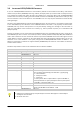
3.9 INITIALISING RS232/FLOW-BUS INTERFACE
If you use a RS232/FLOW-BUS interface for communication (without the micro-switch and 2 LED’s), note that this
module is not part of the (FLOW-BUS) token-ring network, directly at power-up. This means that it is always necessary
to re-initialise the module when power has been interrupted! This is not the case when using an RS232/FLOW-BUS
interface with micro-switch, red LED, green LED and RJ45 connector for FLOW-BUS. By means of the switch you may
force the interface to find a free address on the FLOW-BUS once. You may skip the initialisation and start directly
sending messages.
Also when using digital (Multibus) instruments with RS232 directly on the instrument it is not needed to initialise (give
a free node-address to) the instrument on the FLOW-BUS because instrument is not physically connected to the
FLOW-BUS, but only uses the same protocol. You may start directly sending your messages to the instrument on
either the node-address of the instrument in its memory e.g. node 3 (selective response) or to node-address 128
(always response).
At power-up situation you can communicate with the RS232 interface only at the RS232 side via node 0. To get part of
the FLOW-BUS you have to send an init command, send the network parameters PNA, SNA, NNA, LNA and BM and
send a reset command. From this moment the interface is part of the FLOW-BUS. Ensure the module gets a free and
unique address on the bus, 2 modules on the same address will cause communication problems. When you are sure
that there are no more interfaces in the system, simply force the RS232/FLOW-BUS interface to address 1. This
address is reserved for an interface. PC-support software (FLOWB32.DLL) will search for a free address on which the
interface will be installed.
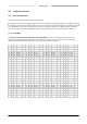
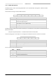
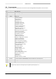
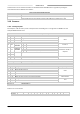
Follow the steps below to realise correct initialisation for this interface via RS232:
Initialisation RS232 interface (needed for FLOW-BUS/RS232 interfaces without switch and LED’s only)
Send
Response
Comment
:050001000A49\r\n
Init instruction for node 0 process 0.
:04000000XX\r\n
No error.
:050001000101\r\n
PNA = Primary Node Address = 1
:04000000XX\r\n
No error.
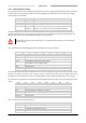
:05000100027F\r\n
SNA = Secondary Node Address = 127
:04000000XX\r\n
No error.
:050001000302\r\n
NNA = Next Node Address = 2
:04000000XX\r\n
No error.
:050001000420\r\n
LNA = Last Node Address = 32 (depends on system size)
:04000000XX\r\n
No error.
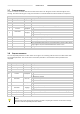
:050001000502\r\n
BM = Bus Management = 67
67 = everything automatically (auto arbitration + gap skipping)
3 = auto arbitration
2 = always bus master
1 = temporary
In older systems: when no R/C-modules in system make BM = 2,
when R/C-modules in system (already bus masters present) than
make BM = 1; otherwise make = 67
:04000000XX\r\n
No error.
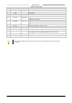
:050001000A52\r\n
Reset instruction for module; from this moment on module will be
active on FLOW-BUS at node address = PNA
:04000000XX\r\n
No error.
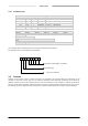
• Sometimes it could be necessary to repeat the first instruction. Wait approx. 2 seconds before
sending the next command.
•
XX means: don’t care
Page 19 RS232 interface 9.17.027