SG-1 Service Gateway System User Manual Document Number: SG1-UM-8500-03
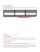
REVISION HISTORY The Revision History provides a summary of any changes in this manual. Please make sure you are using the latest revision of this manual. June 30, 2006 Revision Release Date Revisions Made 01 January 26, 2005 Initial Release 02 August 5, 2005 Revisions to various first-level and second-level commands. Addition of new Appendix: “SG-1 Vendor Specific Attributes.” 03 June 30, 2006 Software Upgrade. This manual is available online at ADC’s website (www.adc.
Table of Contents About This Manual ..........................................................................................................xi Introduction ...............................................................................................................................xi Organization ..............................................................................................................................xi Intended Audience ................................................................
Table of Contents June 30, 2006 Chapter 5: Using the Command Line Interface ........................................................... 5-1 Configuring the SG-1 ............................................................................................................... 5-1 Logging On ............................................................................................................................... 5-1 Logging Off ..............................................................................
June 30, 2006 Table of Contents Appendix B: Redirection Server ................................................................................. B-1 ORUP Commands ................................................................................................................... B-3 Service Name Commands ....................................................................................................... B-4 TFTP Commands ...................................................................................
Table of Contents vi June 30, 2006 SG1-UM-8500-03
List of Figures Figure 1-1. SG-1 10U .......................................................................................................... 1-2 Figure 2-1. Straight-Through and Cross-Over Cable Pin-Outs ...........................................
List of Figures viii June 30, 2006 SG1-UM-8500-03
List of Tables Table 1-1. Packing List ......................................................................................................... 1-4 Table 1-2. System Installation Notes .................................................................................... 1-4 Table 1-3. Possible SG-1 Options ........................................................................................ 1-6 Table 2-1. RJ-45 Pin-Outs .....................................................................................
List of Tables x June 30, 2006 SG1-UM-8500-03
ABOUT THIS MANUAL INTRODUCTION This manual applies to ADC's Service Gateway (SG) system, hereafter referred to as "SG-1." This document includes an overview of the platform, installation procedures, and an SG-1 commands reference. ORGANIZATION This manual includes the following chapters: Chapter Description Chapter 1: Overview Details features and pre-installation requirements for the SG-1 platform, including site requirements for power and cabling.
About This Manual June 30, 2006 CONVENTIONS The following style conventions and terminology are used throughout this guide. Element Meaning Bold font Text that you must input exactly as shown (e.g., type 1 for card 1), menu buttons (e.g., ACCEPT SHELF OPTIONS) or menu screen options (e.g., ALARMS screen) that you must select Italic font Variables that you must determine before inputting the correct value (e.g., Password ) Monospace font References to screen prompts (e.g., Invalid Password...
Chapter 1 OVERVIEW The SG-1 is a service creation platform optimized for delivering differentiated services to residential, mobile, and private subscribers. The SG-1 enables service providers to offer attractive new services that can be selected dynamically and automatically by their wireless, dial-up and broadband users. The SG-1 can provide services over existing infrastructure, integrating smoothly with leading network access servers, RADIUS servers, databases, and billing systems.
Chapter 1: Overview June 30, 2006 The SG-1 comprises two types of system chassis: 1U and 10U. The 1U chassis (or Mini System Chassis) has 2 service creation slots and 1 power supply slot built into the chassis. The 10U chassis (or Full-Size System Chassis) has 16 service creations slots and 4 power supply slots for load sharing redundancy (see Figure 1-1). Figure 1-1.
June 30, 2006 Chapter 1: Overview • Identify any required procedures and tests. • On an equipment plan, make a preliminary decision that locates each of the SG-1 chassis that you plan to install. • Read this manual, whether you are replacing or adding a SG-1 chassis that is being installed. • Verify the list of replaceable parts for the installation (screws, bolts, washers, and so on) so that the parts are identified (see Table 1-1 on page 1-4).
Chapter 1: Overview June 30, 2006 Table 1-1. Packing List Item Catalog/Part Number SG-1 Service Gateway System Chassis SG-1 Service Gateway System User Manual SG-1 Service Gateway System Installation Kit • Ten (10) 6-32 x 3/16 screws: • Two (2) 8-32 x 5/16 screws: • Eight (8) 12-24 x 3/8 screws: • Two (2) mounting brackets • One (1) #6 ground cable • DB9/RJ45 “F” connector Table 1-2.
June 30, 2006 Chapter 1: Overview REQUIRED TOOLS AND EQUIPMENT The following tools are required to install the SG-1 chassis: • Grounding or ESD-preventive wrist strap • No. 2 Phillips-head screwdriver • Multimeter (for continuity testing) • Wire stripper • Wire-wrap tool • Box cutter • #26 AWG wire SPECIFIC SG-1 CHASSIS INSTALLATION REQUIREMENTS The SG-1 chassis dimensions are: • Height of 17.50 inches (44.4 cm) (10U) • Width of 19.0 inches (44.
Chapter 1: Overview June 30, 2006 Table 1-3. Possible SG-1 Options If you want to add: Then: SG-1 chassis Consider installing the first chassis in the top position of a rack to allow for further expansion below it. Fast Ethernet Port Add a Rear I/O card on the corresponding rear slot of an SCC that Fast Ethernet access is desired. Service Creation Cards: VRRP Use an SCC of the same type in any slot (1 through 16).
June 30, 2006 Chapter 1: Overview Chassis Ground and Power Cabling The recommended cabling to ground the SG-1 chassis is 6 AWG (minimum) stranded copper wire. For the SG-1 chassis, the recommended cabling is 14 AWG (1.88 mm diameter) stranded copper or 14 AWG (1.628 mm diameter) solid wire to connect the DC terminal block to the facility provided power.
Chapter 1: Overview 1-8 June 30, 2006 SG1-UM-8500-03
Chapter 2 INSTALLATION This chapter provides detailed information about installing the SG-1. MOUNTING THE SG-1 CHASSIS To mount the SG-1, complete the following procedure. Step Action 1 If required, securely attach the customer provided rack adapters to the left and right sides of the rack in which the SG-1 chassis will be installed. 2 Position the chassis in the rack. 3 Align the chassis adapter holes with the vertical rack mounting holes.
Chapter 2: Installation June 30, 2006 Connecting AC Power to an SG-1 AC Chassis Connect an AC power cord(s) to AC power connectors, as required. Step Action 1 Turn off the AC power switch on the back of the SG-1 AC chassis. 2 Plug the power cord into the chassis power connector. 3 Connect the AC power cord from the power supply to the facility power source. Do not turn on the power switches at this time.
June 30, 2006 Chapter 2: Installation Table 2-1. RJ-45 Pin-Outs MDI Pin Number Signala MDI-X Pin Number Symbol Direction 1 3 Transmit Data (+) TX+ (TX0+) Out(Bidirect) 2 6 Transmit Data (-) TX-(TX0-) Out(Bidirect) 3 1 Receive Data (+) RX+(TX1+) In(Bidirect) 4 4 NC (TX2+) (Bidirect) 5 5 NC (TX2-) (Bidirect) 6 2 Receive Data (-) RX-(TX1-) In(Bidirect) 7 7 NC (TX3-) (Bidirect) 8 8 NC (TX3+) (Bidirect) case case Chassis Ground a.NC = no connection.
Chapter 2: Installation June 30, 2006 Connecting to an Ethernet Port Step Action 1 Plug the RJ-45 connector of the Ethernet cable into the FAST E-NET port on the SG-1 chassis back panel. 2 Connect the other end of the cable into the Ethernet port on the PC, hub, or other Ethernet device. CONNECTING THE CRAFT PORT INTERFACE In situations where a Rear I/O card is installed, the default craft port is on the Rear I/O card.
June 30, 2006 Chapter 2: Installation Installing Blank Faceplates Use the blank faceplate identified in the “Blank Faceplate Requirement” on page 1-6. IMPORTANT ! Install blank faceplates in the SG-1 chassis to cover unused slots. Unused slots must be covered to prevent personnel contact with back panel connectors under power and to maintain proper airflow within the chassis. Step Action 1 Slide the blank faceplate into the empty slot. Ensure the retaining latches are lifted.
Chapter 2: Installation 2-6 June 30, 2006 SG1-UM-8500-03
Chapter 3 COMMAND-LINE INTERFACE (CLI) This chapter describes the SG-1 Command-Line Interface (CLI), the steps to access the CLI, and the steps to perform initial configuration using the CLI. OVERVIEW The SG-1 Service Gateway System management interface is accessed using a CLI, which provides comprehensive SG-1 system management including configuration, performance monitoring, and system maintenance and administration.
Chapter 3: Command-Line Interface (CLI) Menu June 30, 2006 Types of Commands Debug Use the commands in this first level menu to display system parameters such as: • Memory allocation • Network/tunnel connections • Sonet clock source Configuration-Debug Use the commands in this third level menu to configure system debug messages such as: • Error and event level • Time server IP address • Log server IP address COMMANDS AND NAVIGATION Navigate the command-line interface by entering a command name or a
June 30, 2006 Chapter 3: Command-Line Interface (CLI) COMMAND-LINE EDITING The command-line interface provides a DOS-like environment for editing. It provides special key functions and other special functions developed for a VT100-type terminal. Note: Commands may not be recognized under some vendor's versions of Telnet.
Chapter 3: Command-Line Interface (CLI) 3-4 June 30, 2006 SG1-UM-8500-03
Chapter 4 ACCESSING THE COMMAND LINE INTERFACE The initial step for managing the SG-1 Service Gateway System is to log on locally to an SCC or rear I/O port (if a rear I/O card option is used) and set an IP address to allow for remote management via a Telnet session. This IP address should place the SG-1 system on the same subnet as a router or other device to which it connects upstream through its Ethernet port. CONNECTING TO THE CRAFT PORT Complete the following procedure to connect to the Craft port.
Chapter 4: Accessing the Command Line Interface Step June 30, 2006 Action 3 Press ENTER to initiate the terminal session. 4 Enter your user name at the Username: prompt. 5 Enter your password at the Password: prompt.
June 30, 2006 Chapter 4: Accessing the Command Line Interface Parameter(s) \ The SCC and rear I/O interfaces have specific designations as shown in Table 4-2. Table 4-2. Interface Identification Card/Type Slot/Port 1 Slot/Port 2 Rear I/O 1/1 1/2 Gigabit Ethernet 1/1 1/2 ATM 2/1 2/2 GiG-E 1/1 1/2 ATM/GiG-E Card The SCC IP address for interface in question.
Chapter 4: Accessing the Command Line Interface June 30, 2006 DISPLAYING THE IP ADDRESS Host> show configuration From the Host> prompt, enter the show configuration command to verify your configuration. Example(s) Host> show configuration … interface ethernet 0\1 192.168.0.1 255.255.255.0 mode auto ip default-gateway 192.168.0.
Chapter 5 USING THE COMMAND LINE INTERFACE There are multiple ways to access an SG-1 for management. Also, there are rules that determine the number of accesses that can be made at one time to an SG-1 system. Once you have access, you can complete the configuration and management of the SG-1. CONFIGURING THE SG-1 The operational software for an SCC resides on each individual card. The software is accessed through a command-line interface to configure and manage an SG-1.
Chapter 5: Using the Command Line Interface June 30, 2006 WHAT TO DO NEXT From the command-line interface, use the procedures in this manual to (among other things): • Configure the network card ports, followed by services for the network connections, including Automatic Protection Switching (APS) for the OC3 card. • Configure ATM traffic, including traffic profiles, policing, packet discard, over-subscription, and traffic shaping for Unspecified Bit Rate (UBR) traffic.
Chapter 6 FIRST-LEVEL COMMANDS This chapter describes the commands available at the first command level of each SCC. You can enter the entire command or the first two letters of most commands and command-line arguments. If there are two commands with the same first two letters, enter enough letters to differentiate between the two commands. The remaining letters can be displayed, if you wish to see the complete command, by pressing TAB after the first two letters.
Chapter 6: First-Level Commands June 30, 2006 SHOWING A LIST OF AVAILABLE PARAMETERS Using the GREP command The GREP command may be operated on any of the system commands. Usage system-command | grep "string" Example(s) Host> show users | grep "moshe" 1 ANet PPP moshe 192.168.2.12 00:04:23 9568432 Host> Host> write terminal |grep "interface" interface loopback 1 10.1.208.1 255.255.255.0 interface ethernet 0\2 1.1.1.1 255.255.255.
June 30, 2006 Chapter 6: First-Level Commands Example(s) Host> ? show - Display running configuration and status write - Write running configuration copy-TFTP - copy-TFTP file from server ping - Ping command reload - Reload the system clear - Disconnect line traceroute - Traceroute command exit - Exit SG-1 management session configure - Modify running configuration debug - Show debug information Host> Using the show ? command Host> show ? From the first-level Host> prompt, enter show ?
Chapter 6: First-Level Commands June 30, 2006 These commands are discussed below. Using the show version command Host> show version Enter show version to see version levels of hardware and software. Usage show version show version software show version hardware <2> Parameter(s) The first-level parameter has three options: • software–Displays the software version of the SCC in question. • hardware–Displays hardware information of the SCC in question.
June 30, 2006 Chapter 6: First-Level Commands Example(s) Host> show version software Module Num Application ______ ___ ___________ SCC-ATM155 1 10.0T2.05 Jun 08 2006 17:18:19 Host> Host> show version hardware Module Num Part No. Serial No. Slot _________ ___ _____________________ __________ ____ 2079600287 1 Backplane SCC-ATM155 1 2 710-200-0 Rev 0 0 650-038 Rev 1 Host> Host> show version hardware 2 Service Creation Card with 256MByte memory module Module Num Part No.
Chapter 6: First-Level Commands June 30, 2006 Displaying the configuration in NVRAM Host> show configuration Usage show configuration 6-6 SG1-UM-8500-03
June 30, 2006 Chapter 6: First-Level Commands Example(s) Host> show configuration # version: 10.0T2.05 Jun 08 2006 17:25:51 interface ethernet 0\1 172.16.1.13 255.255.255.128 auto interface ethernet 0\2 172.16.13.193 255.255.255.128 auto password viewer Tw)wtxpassword operator Tw)wtxpassword superuser +5z!#r-MGA password technician Koz!# password pre-authentication +k(~#i+^#43\,6 def-service-auth ppp-auto multilink-mode multi-cage radius-server host 172.16.1.
Chapter 6: First-Level Commands June 30, 2006 ip local-pool pool1 162.10.1.1 162.10.1.254 internal ip domain-name POPmaestro ip primary-name-server 62.90.133.233 ip secondary-name-server 0.0.0.0 ip default-gateway 172.16.1.1 ip tcp adjust-mss on ip dhcp relay server Ethernet 0\2 1 172.16.1.15 debug watchdog-TimeValue 60 time-server-ip 0.0.0.0 error-level default 3 output-device console event-level default 5 output-device console trace default off sysLog-server-ip 192.168.1.
June 30, 2006 Chapter 6: First-Level Commands Displaying Ethernet port configurations Host> show terminal Displaying Ethernet Port Statistics Host> show ethernet 0 \ 1 Use the show ethernet command to display the Ethernet port parameters for the Rear I/O Ethernet port. Note: When keying in the command, the backward slash ‘\’ is optional. The command will work with just a space between the slot number and port number.
Chapter 6: First-Level Commands June 30, 2006 Example(s) Host> show ethernet 0 \ 1 Interface Slot 0 Port 1 is up, line protocol is up Hardware address is 008042195FB7 Internet address is 10.0.1.220 Mask is 255.255.255.0 Gateway IP address is 10.0.1.
June 30, 2006 Chapter 6: First-Level Commands Displaying SONET port status Host> show port sonet Usage show port sonet Parameter(s) None.
Chapter 6: First-Level Commands June 30, 2006 Displaying ATM Port Status Host> show atm pvc Usage show atm pvc Parameter(s) None.
June 30, 2006 Chapter 6: First-Level Commands Displaying User Status Host> show user Usage show [|] Parameter(s) [] The line number of the user to be viewed. Example(s) Host> show users Line Line Type User User Name IP Address Type Duration Calling hh:mm:ss Number ____ ____ ____ __________ __________ ________ _______ 52 PPP 155.226.20.
Chapter 6: First-Level Commands June 30, 2006 Host> show users 704 Line number: 702 Line type: ANet User type: PPP User name: 0_220 IP address: 10.220.3.191, IP pool name: 1 Next Hop: 10.0.1.253 Tunnel ID(in): 4798 Tunnel Session ID(in): 21182 LAC source IP 10.0.1.
June 30, 2006 Chapter 6: First-Level Commands Displaying Routing Tables Host> show ip-route Use this command to display the configured routes. Usage show ip-route Parameter(s) None. Example(s) Host> show ip-route Network NetMask Gateway ___________ _____________ ___________ __________________ 155.226.21.0 255.255.255.0 0.0.0.0 Ethernet [ 0\2 ] 155.226.22.128 255.255.255.128 0.0.0.
Chapter 6: First-Level Commands June 30, 2006 Displaying System Parameters Host> show system Usage show system show system Parameter(s) Calculates the throughput through each interface in Mbps.
June 30, 2006 Chapter 6: First-Level Commands Host> show system load Calculating load ... Total current connected users: 0 Total sessions' capacity: 2000 System load: 0% CPU usage: 1% Interface 0/2 Throughput [5 sec. Avg.]: 0.0 Mbit/s In, 0.0 Mbit/sec Out Total available throughput: 100 Mbit/s In, 100 Mbit/sec Out Traffic Usage: In 0.0%, Out 0.0% Interface 1/1 Throughput [6 sec. Avg.]: 0.0 Mbit/s In, 0.0 Mbit/sec Out Total available throughput: 1000 Mbit/s In, 1000 Mbit/sec Out Traffic Usage: In 0.
Chapter 6: First-Level Commands June 30, 2006 Displaying License Attributes Host> show license This command displays the system license information. Usage show license Parameter(s) None.
June 30, 2006 Chapter 6: First-Level Commands Example(s) Host> show license Working license : permanent Temp License Magic: T001001086 [CREATION] DATE=December 22 2005 16:03:57 [VERSION] MAJOR=10 [SN] SNSOURCE=1 SNNUM=1 SN1=6046838 [MAGIC] Magic String=C000000067 MaxAllowedDays=30 [OPTIONS] Allow Maximum 500 Users=off Allow Maximum 1000 Users=off Allow Maximum 2000 Users=on Allow Maximum 4000 Users=off Gigabit Ethernet=on ATM=on Pre Paid=on Bandwidth Control=on Hierarchical Bandwidth Control=on Customized
Chapter 6: First-Level Commands June 30, 2006 Filter Redirection=on Location Based Service=on Service Selection=on Native IP=on Dynamic IP Changing=on Application Awareness=on MPLS=on Native IP Roaming=on Host> 6-20 SG1-UM-8500-03
June 30, 2006 Chapter 6: First-Level Commands Displaying VRRP attributes Host> show vrrp interface Use this command to display the configured Virtual Router Redundancy Protocol (VRRP) status on the specified interfaces. Usage show vrrp interface (|) Parameter(s) (|) The interface will be either an Ethernet or VLAN interface. Slot number; valid values are 0 to 3. Defines the port; valid values are 1 or 2.
Chapter 6: First-Level Commands June 30, 2006 For the backup: Host> show vrrp interface Ethernet 0\1 Ethernet 0\1 - Group 1 State is Backup Virtual IP address is 192.168.1.1 Master router is 192.168.1.2 Virtual MAC address is 00-00-5E-00-01-01 Advertisement interval is 1 seconds Priority 100 Preemption mode: on Host> Displaying active GRE and IP-in-IP tunnels Host> show ip-tunnel This command displays the active GRE and IP-in-IP tunnels in the system.
June 30, 2006 Chapter 6: First-Level Commands Example(s) Host> show ip-tunnel Tunnel IP Tunnel Total Endpoint Sessions Tunnel Tunnel Status Type --------------- ---------- -------- ------- -----192.168.1.1 remote 20 unknown gre 10.10.2.234 remote 11 up ip-in-ip 10.10.1.20 remote 7 down ip-in-ip Host> Host> show ip-tunnel ip-in-ip Tunnel IP Tunnel Total Endpoint Sessions Tunnel Tunnel Status Type --------------- ---------- -------- ------- -----10.10.2.
Chapter 6: First-Level Commands June 30, 2006 Displaying show mpls-labels commands Host> show mpls-labels It displays the incoming labels binding received from the neighbors and the out-going label binding distributed by the system. When no specific FEC is defined, the system shows all FECs. Usage Show mpls-labels [] Parameter(s) Standard labels are the first labels on the stack, while vc labels (tunnels) are the second lable on the stack.
June 30, 2006 Chapter 6: First-Level Commands VC in for Martini draft: Host> show labels vc in VC ID VC Type Group ID Label Tunnel Endpoint Upper stack FEC ID 1 LAN 0xc2010000 123876 192.0.1.8 1 2 LAN 0xc2010000 123876 192.0.1.8 1 1 VLAN 0xc2010001 1034 212.1.3.4 2 1 PPP 0xc2010002 1035 195.3.4.5 3 VC OUT for Martini draft: Host> show labels vc OUT VC ID VC Type Group ID Label Tunnel Endpoint 1 LAN 0xc2010000 123876 192.0.1.8 2 LAN 0xc2010000 123876 192.0.1.
Chapter 6: First-Level Commands June 30, 2006 Displaying show mpls l2transport vc commands Host> show mpls l2transport vc It shows confine redirected interface traffic through MPLS l2vpn tunnel based on Martini draft. Example(s) Host> show mpls l2transport vc Dest address VC ID Status Type 194.90.1.4 200 UP redirect 194.90.1.4 201 UP redirect Displaying a list of available write commands Host> write ? This command shows the available write commands enabled on the SCC.
June 30, 2006 Chapter 6: First-Level Commands Example(s) Host> write terminal # version: 10 May 21 2006 15:14:31 password viewer Tw)wtxpassword operator Tw)wtxpassword superuser +5z!#r-MGA password technician Koz!# password pre-authentication +k(~#i+^#43\,6 def-service-auth ppp-auto multilink-mode multi-cage radius-server key netix SNMP-server community get T}y||g SNMP-server community set T}y||g banner BannerString session-timeout 64800 idle-timeout 1800 service cache on aging-time 10 service internal f
Chapter 6: First-Level Commands June 30, 2006 Using the copy-TFTP command Host> copy-TFTP flash Use this command to copy a new application software (image) or license file from a TFTP server to the flash memory of the SCC-ETH card. Usage copy-TFTP flash [ | ] Note: The SG-1 as a service creation machine uses a license mechanism, which enables the activation and deactivation of specific services.
June 30, 2006 Chapter 6: First-Level Commands The destination ip address to ping. [-c ] The number of echoes. [-i ] The number of wait seconds. [-s ] The number of bytes. [atm] The ATM interface. [atm ] The ATM slot number (ATM uses slot 2). [atm ] The ATM port number (either port 1 or port 2). [atm ] The ATM sub-interface number. [atm ] The ATM vpi number. [atm ] The ATM vci number.
Chapter 6: First-Level Commands June 30, 2006 Using the reload command to restart the system Host> reload non-graceful Use the reload non-graceful command to reset the system and reload the software. Using this command will terminate all sessions. Usage reload non-graceful Parameter(s) None. Example(s) Host> reload non-graceful Resetting the system in 10 seconds...
June 30, 2006 Chapter 6: First-Level Commands Clearing Users Host> clear user A specific user can be disconnected from the SG-1 by writing the clear user command followed by its line number. Usage clear user Note: You can use the show user command to determine the list of connected users. Note: If the user is a multi-link user, the following message will appear: Note that multi-link users may have other lines that are still connected.
Chapter 6: First-Level Commands June 30, 2006 Using the Traceroute Command Host> traceroute Use the traceroute command to track the route a packet takes to a network host. Usage traceroute [-h | -i ] Parameter(s) The IP address to which the trace is to be performed. [ -h ] The maximum number of hops to be attempted (max = 30). [ -i ] The max. number of seconds to wait for a response. Example(s) Host> traceroute 155.226.10.
June 30, 2006 Chapter 6: First-Level Commands Using the exit command Host> exit This command exits the user from the current configuration level. When used at the first level, the user is logged out of the session. Usage exit Parameter(s) None.
Chapter 6: First-Level Commands June 30, 2006 USING DEBUG MODE This section provides information on the commands and options available in debug mode. Switching to Debug Mode Host> debug Use the debug command at the first-level prompt (Host>) to switch the system to the second-level debug prompt: Host(debug)#. This prompt indicates that the user is now in the second-level debug mode and has access to the five second-level commands in the debug menu.
June 30, 2006 Chapter 6: First-Level Commands Using the show command in debug mode Host(debug)# show Use the show command to display memory, system, and fragmentation information. Usage show [memory | system |log-modules | statistics | arp] Parameter(s) [memory] Display memory allocation. [system] Display connection information. [log-modules] Display system log modules. [statistics] Display fragmentation information. [arp] Display ARP information table.
Chapter 6: First-Level Commands June 30, 2006 Example(s) Host(debug)# show statistics fragmentation Total number of packets that were fragmented: 0 Total number of packets that were reassembled: 0 Total number of upstream packets in which the MSS field was adjusted: 0 Total number of downstream packets in which the MSS field was adjusted: 0 Host(debug)# Host(debug)# show system Up-time: 4 Days, 20 Hours, 56 Minutes, 12 Seconds Total number of: Network incoming calls: 0 Network calls in which PPP
June 30, 2006 Chapter 6: First-Level Commands Host(debug)# show log-modules Group Error Error Name Event Event Trace Min Max Min Max AAA 0 DEF 0 DEF DEF User 0 DEF 0 DEF DEF IP 0 DEF 0 DEF DEF Route 0 DEF 0 DEF DEF System 0 DEF 0 DEF DEF PPP 0 DEF 0 DEF DEF Service 0 DEF 0 DEF DEF NativeIP 0 DEF 0 DEF DEF Interface 0 DEF 0 DEF DEF L2TP 0 DEF 0 DEF DEF SG1-UM-8500-03 6-37
Chapter 6: First-Level Commands Module Group Error Name Name Min ABM User AbmFSM June 30, 2006 Error Event Event Trace Max Min Max 0 DEF 0 DEF DEF User 0 DEF 0 DEF DEF AbmIpPool User 0 DEF 0 DEF DEF AbmMlPPP User 0 DEF 0 DEF DEF AbmRadius AAA 0 DEF 0 DEF DEF AbmService User 0 DEF 0 DEF DEF AbmRadiusProxy AAA 0 DEF 0 DEF DEF EDS Service 0 DEF 0 DEF DEF PPP PPP 0 DEF 0 DEF DEF PPPWrapper PPP 0 DEF 0 DEF DEF PPPService PPP 0
June 30, 2006 Chapter 6: First-Level Commands show arp command This command displays the arp table information. Host(debug)# show arp Usage Show arp [] Parameter(s) The interface on which this entry’s equivalence is effective. Numbers are 1 to 65,000. This is the IP address corresponding to the media-dependent “physical address. It should be a legal IP address. Example Host(debug)# show arp IfIndex PhyAddress NetAddress MediaType 1 000000000000 127.0.0.
Chapter 6: First-Level Commands June 30, 2006 Clear arp command It clears the arp table entry (only dynamic entries), the clear arp specific, clears any entry except the static ones. Note: when deleting a non-volatile arp entry the system might re-creates it as a dynamic entry. Usage Clear arp [arp-specific ] Parameter(s) This is the interface on which this entry’s equivalence is effective. Numbers are 1 to 65,000.
June 30, 2006 Chapter 6: First-Level Commands Host(debug)# show memory Free memory: region 0: 9583616 region 1: 56918016 Largest memory : region 0 buffer: 9583616 region 1 buffer: 56901632 pNA statistics: Number of classes: 0 Buffer size 0 Buffer size 32 Buffer size 64 Buffer size 128 Buffer size 256 Buffer size 512 Buffer size 1024 Buffer size 2048 - 8 - blocks: 15000 free: 12492 wait: 0 drops: blocks: blocks: blocks: blocks: blocks: blocks: blocks: blocks: 9000 2048 512 768 512 128 256 48 fre
Chapter 6: First-Level Commands June 30, 2006 Defining port-ethernet redundancy-mode command Host(debug)# port-ethernet redundancy-mode It immediately activates the Ethernet redundancy operation. Usage port-ethernet redundancy-mode \ [] Parameter(s) [working slot] It is the working, Ethernet interface slot number; legal values include 0 and 1.
June 30, 2006 Chapter 6: First-Level Commands Checking the system RADIUS interface Host(debug)# radius-server check This command checks the system RADIUS interface, by authenticating user-name and password the same way the system authenticates a connected call (including retries and RADIUS redundancy). Usage radius-server check auth-type [] Parameter(s) Username to be validated at the RADIUS server. Password to be validated at the RADIUS server.
Chapter 6: First-Level Commands 6-44 June 30, 2006 SG1-UM-8500-03
Chapter 7 SECOND LEVEL COMMANDS This chapter describes the primary commands available at the second command level. For additional second level commands, refer to Appendix B: Redirection Server. Note: Some non-applicable information was removed from sample screens for ease of viewing. Using the configure command Use the configure terminal command at the first level prompt to switch the system to the second-level configuration prompt, Host(config)#.
Chapter 7: Second Level Commands June 30, 2006 Example(s) Host> configure network 155.226.20.250 filename Loading file ... Preparing TFTP download...Done. Starting the TFTP download....completed(downloaded size is 892 ). Converting file ...
June 30, 2006 Chapter 7: Second Level Commands BANNER COMMAND Creating a Login Banner You may create a greeting message or banner, to be displayed on the user's terminal when they log in. The banner may be a string of up to 32 alphanumeric characters. To set "Welcome to SG-1" as a banner: At the second level command prompt, type: banner Welcome to SG-1 (then press ENTER).
Chapter 7: Second Level Commands June 30, 2006 The operating mode of the interface to be configured (see Table 7-2). (mtu) The maximum transmission unit. Select either: • 1500 (default) • 1544 Example 1 Host(config)# interface ethernet 0 \ 2 12.3.66.211 255.255.255.0 auto mtu 1500 interface ethernet 0 \ 2 12.3.66.211 255.255.255.
June 30, 2006 Chapter 7: Second Level Commands Table 7-2. Ethernet Operating Mode Value Explanation 10 H 10M half-duplex 10 F 10M full-duplex 100 H 100M half-duplex 100 F 100M full-duplex 1000 H 1000M half-duplex 1000 F 1000M full-duplex auto auto sensing Host(config)# no interface Ethernet Usage no interface Ethernet \ Parameter(s) This is the interface slot number you want to configure.
Chapter 7: Second Level Commands June 30, 2006 Configuring Ethernet Redundancy The system supports redundancy between 0\1 and 0\2 ethernet interface or between 1\1 or 1\2 Ethernet interface. The system, automatically while detects a malfunction in the working Ethernet (for example link down), switches to the protecting (redundant) Ethernet interface. Using the port-ethernet redundancy-enable command Host(config)# port-ethernet redundancy-enable Use this command to configure Ethernet port redundancy.
June 30, 2006 Chapter 7: Second Level Commands Example(s) Host (config) # port-ethernet redundancy-enable 1\1 1\2 non-revertive Note: The system should refuse to enable Ethernet redundancy mode in case the protecting Ethernet interface is configured. It should indicate such kind of command failure to the system log and to the user interface (telnet/console).
Chapter 7: Second Level Commands June 30, 2006 LOOPBACK COMMANDS Configuring interface loopback Host(config)# interface loopback This command enables the administrator to either add or change the loopback interface. Note: The loopback interface can be part of the IP route lines/commands. Usage interface loopback Parameter(s) This is the interface number of the loopback; the valid range is 1 to 200.
June 30, 2006 Chapter 7: Second Level Commands Example(s) Host(config)# interface loopback 1 192.168.3.4 255.255.255.255 Note: When assigning the loopback interface an address that is in the subnet of one of the system interfaces the system should ignore the command and indicates the reason. Host(config)# interface loopback 1 192.168.3.4 255.255.255.0 The loopback address is not valid.
Chapter 7: Second Level Commands June 30, 2006 Usage interface vlan \ \ [name | QinQ ] Parameter(s): Slot number of the physical card. Port number of the card (1 or 2). VLAN interface identifier; valid number range is 1 to 4095. IP address for the VLAN. Subnet mask for the VLAN.
June 30, 2006 Chapter 7: Second Level Commands Using no interface VLAN command Host(config)# no interface vlan This command deletes a VLAN definition for the Ethernet interface. Usage no interface vlan \ < id> Parameter(s) This is the slot number of the physical card. This is the port number of the card (1 or 2). This is the VLAN interface identifier; valid number range is 1 to 4095.
Chapter 7: Second Level Commands June 30, 2006 Setting the default-service authentication mode Host(config)# def-service-auth When using authentication by username and password two protocols are available: • PAP (Password Authentication Protocol)–the most basic form of authentication. In PAP, a user's name and password are transmitted over the network and compared to a table of name-password pairs. The main disadvantage of PAP is that both the username and password are transmitted without encryption.
June 30, 2006 Chapter 7: Second Level Commands Changing domain authentication settings Host(config)# domain-authentication In a SG-1 system, virtual private tunnels (VPNs) are created upon RADIUS request. The tunneling service is always enabled within the SG-1 (there is no configuration command for turning it on or off). The domain-authentication configuration command is used to enable and disable authentication of the user's domain.
Chapter 7: Second Level Commands June 30, 2006 Example 1: Host(config)# authentication web-auth-method CHAP Host(config)# end Host # write terminal. authentication web-auth-method CHAP ... The “no” command set the system web authentication mode to PAP. Host(config)# no authentication web-auth-method Example 2: Host(config)# no authentication web-auth-method Host(config)# end Host # write terminal ...
June 30, 2006 Chapter 7: Second Level Commands Usage port sonet \ type (OC3c|STM1) Parameter(s) The line card slot to be configured. Use the value 2 to indicate the configuration of the SONET/SDH port. The line card port to be configured (either 1 or 2). (OC3c|STM) The type of physical interface: • OC3c–the North American standard for 155.52 Mbps data over optical fiber. • STM–the standard for 155.52 Mbps data over optical fiber outside of North America.
Chapter 7: Second Level Commands June 30, 2006 The port number to be designated as the protect port (valid value = 1 or 2). [SFBER (value)] Signal Fail Bit Error Rate Threshold. Valid values = 3 to 12, Default = 3. [SDBER (value)] Signal Degrade Bit Error Rate Threshold. Valid values = 5 to 12, Default = 5.
June 30, 2006 Chapter 7: Second Level Commands [loopback] Places a logical loopback on the bridge-route interface. Numeric value assigned to the bridge-route loopback. [mtu] Used to set the interface's Maximum Transmission Unit (MTU) (valid values are 1500 or 1544). Example(s) Host(config)# interface atm 2 \ 1 \ 1 type bridge-route point-to-point ip 192.168.10.1 255.255.255.
Chapter 7: Second Level Commands June 30, 2006 Using the no pppoa enable command Host(Config)# no pppoa enable interface The no pppoa enable interface command disables PPPoA negotiation for a specific interface in the system. Usage No pppoa enable interface \ For parameters see Table 7-6. Using the interface atm command Host(config)# interface atm The interface atm command defines the atm interfaces in the system.
June 30, 2006 Chapter 7: Second Level Commands Table 7-6.
Chapter 7: Second Level Commands June 30, 2006 Configuring a single PVC Host(config)# atm pvc This command creates a permanent virtual circuit (PVC) on an ATM interface. Usage atm pvc [name ] | [ OAM | ubr ] Parameter(s) The virtual path identifier (valid values 0 - 255). The virtual channel identifier (valid values 32 - 2032). The value 2 is required to select the SONET/SDH interface.
June 30, 2006 Chapter 7: Second Level Commands [OAM] Operation And Management mode • on - Enable OAM mode • off - Disable OAM mode • on-cc - Enable OAM mode with continuity check Example(s) Host(config)# atm pvc 0 \ 60 \ 2 \ 1 \ 1 Added item Host(config)# Configuring a range of PVC’s Host(config)# atm pvc range Use this command to configure a range of PVC's on an ATM interface.
Chapter 7: Second Level Commands June 30, 2006 [OAM] Operation And Management mode • on - Enable OAM mode • off - Disable OAM mode • on-cc - Enable OAM mode with continuity check Example(s) Host(config)# atm pvc range 2 34 38 1 \ 2 \ 65 name arttt oam on ubr 120 RADIUS COMMANDS Configuring the RADIUS server in the SG-1 configuration Host(config)# radius-server Each RADIUS server should be configured in the system. The radius-server command is used to configure the RADIUS server settings.
June 30, 2006 Chapter 7: Second Level Commands Parameter(s) The authentication port number can be any number between 0 and 65535. The default value is 1812. The accounting port number can be any number between 0 and 65535. The acct-port default value is 1813. m (Merit), i (Infovia) or s (Standard) are the three types of RADIUS server. The RADIUS priority can be any number from 1 to 5. Note: From Version 4.
Chapter 7: Second Level Commands June 30, 2006 Example(s) Host(config)# radius-proxy client 25.24.1.99 255.255.255.0 key poiplk auth-port 78 acct-port 589 Using the service cache command Host(config)# service cache The SG-1 is able to cache each received service's information based on a configured aging time. Operating this capability via the service cache command causes the system to authenticate a service once during the specified aging period.
June 30, 2006 Chapter 7: Second Level Commands Parameter Description Loopback interface number. Values 1 - 200 Example(s) Host(config)# ip radius source-interface Ethernet 0 \ 2 Host(config)# ip radius source-interface ATM 2 \ 1 \ 44 Note: The following command is used to configure the SG-1 to issue requests to the RADIUS via the loopback interface (the source address of the packet shall be SG-1's address).
Chapter 7: Second Level Commands June 30, 2006 access-list EDS-permit access-list native-ip native-ip-pass-through After keying in one of the above commands, the system responds by displaying Added item. Parameter(s) There are two options for the first command line argument following the access list command: • Telnet-permit - to allow Telnet access to a SG-1 from a certain IP address.
June 30, 2006 Chapter 7: Second Level Commands Parameter(s) This is the allowed network source IP; it must be a legal network IP address. This is the allowed network source mask; it must be a legal network IP address. Example(s) Host(config)# access-list native-ip 192.168.1.0 255.255.255.0 Using the no access-list native-ip command Host(congfig)# no access-list native-ip This command deletes the native IP access list configuration.
Chapter 7: Second Level Commands June 30, 2006 Example(s) Note: In the following example the whole network 192.168.1.0 is configured as native-ip potential users except for 192.168.1.1, which is probably a server in this network and not a potential user. Host(config)# access-list native-ip 192.168.1.0 255.255.255.0 Host(config)# access-list native-ip-pass-through 192.168.1.1 255.255.255.255 Note: In order to activate the native-ip-pass-through, IP forward command should be defined.
June 30, 2006 Chapter 7: Second Level Commands When using the group parameter, there are three options for the first command line argument: • aaa–Major alarm. Any defined RADIUS server marked in the system DB as dead (inactive) will be reported via SNMP. Any defined RADIUS server marked in the system as ALIVE after being DEAD sends trap indication and log indication. • network–Major alarm. Occurs when Ethernet link is down.
Chapter 7: Second Level Commands June 30, 2006 TUNNEL COMMANDS Host(config)# interface tunnel This command defines a remote (the tunnel initiator) tunnel endpoint IP address, which allowed opening ip-in-ip or GRE tunnels to the system. The local tunnel endpoint ip address (tunnel destination) should be one of the system IP addresses (Ethernet, VLAN, Loopback, or ATM).
June 30, 2006 Chapter 7: Second Level Commands Note: The system should refuse changing a tunnel interface parameter that is already carrying user data. Host(config)# interface tunnel 1 192.168.0.1 10.0.1.7 ip-in-ip Operation error: The tunnel interface parameters cannot be changed since users already using it. You should delete it first The tunnel interface should appear in the ifTable with type tunnel (131) and should include the standard interface information.
Chapter 7: Second Level Commands June 30, 2006 Example(s) Host(config)# no interface tunnel 1 Note: The system should refuse the interface tunnel command when an existing interface already includes the same remote tunnel endpoint IP address, local tunnel IP address, and tunnel type. Host(config)# interface tunnel 1 192.168.0.1 10.0.1.
June 30, 2006 Chapter 7: Second Level Commands TIMEOUTS COMMANDS Timeouts are a used to stop activities if the SG-1 recognizes a problem with data transfer. session-Timeout command Setting the Session-Timeout The session timeout is used to disconnect a user after a specified number of seconds. Usage session-timeout Parameter It is the seconds number, session timeout in seconds 0 - 4250000 (0 = unlimited).
Chapter 7: Second Level Commands June 30, 2006 NATIVE IP COMMANDS Using the native-ip dhcp pre-auth-mode command Host(config)# native-ip dhcp pre-auth-mode The system should enable upon configuration to pre-authenticate a Native IP session, which uses DHCP (DHCP discover) for IP allocation based on its MAC address. A successful pre-authentication will forward the DHCP discover message to the DHCP server. This command defines the system pre-authentication method in a DHCP request for native IP tunnels.
June 30, 2006 Chapter 7: Second Level Commands Example(s) Host(config)# native-ip def-service-auth werbcvxsaq Using the native-ip enable command Host(config)# native-ip enable interface This command enables native ip service on a specific interface. It enables the native IP for a specific VLAN or interface. Phase 1 should include Ethernet interface and VLAN-Id only. Phase 2 should include interface atm.
Chapter 7: Second Level Commands June 30, 2006 Example(s) Host(config)# native-ip enable interface Ethernet 0 \ 1 Host(config)# native-ip enable interface ATM 2 \ 2 \ 43 Host(config)# native-ip enable interface VLAN 0 \ 1 \ 45 The system should disable the native-ip enable command in case Native IP capability is not licensed (set to off).
June 30, 2006 Chapter 7: Second Level Commands Using native-ip realm command Host(config)# native-ip realm The native-ip realm command specifies the realm string the system should use in the native-ip authenticating, accounting, and service operations. The realm should be added to the user-name field in all native-ip user's authentication and accounting radius messages, except for web-authentication, regardless of its native-ip type (DHCP, Proxy radius, Plain IP).
Chapter 7: Second Level Commands June 30, 2006 Parameter(s) The Ethernet slot number (valid number range is 0 to 2). The Ethernet port number (1 or 2). The Ethernet slot number (valid number range is 0 to 2), The Ethernet port number (1 or 2), and VLAN identifier, sub-interface (valid number range is 1 to 4095). This specifies the LDP IP address of the remote PE; it must be a valid IP address.
June 30, 2006 Chapter 7: Second Level Commands MAXIMUM SEGMENT SIZE (MSS) CHANGING Using the ip tcp adjust-mss command Host(config)# ip tcp adjust-mss The system, when configured so that ip tcp adjust-mss is set to on, should adjust the TCP MSS option value on SYN packets to 1436 (for MSS option larger than 1436) in both directions for each connected user. (Note: When the mtu is configured to 1544, there is no need to adjust the mss.
Chapter 7: Second Level Commands June 30, 2006 L2TP AND PPP COMMANDS The L2TP commands are used for configuring the L2tp source-address. When the l2tp source-address is configured, the system sets the l2tp source address in the response packets regardless of the original l2tp LAC request. Only one source interface may be defined. Using the ip l2tp source-address command Host(config)# ip l2tp source-address This command deletes the radius source-interface configuration by setting it to its default value.
June 30, 2006 Chapter 7: Second Level Commands Configuring the primary DNS Host(config)# ip primary-name-server Usage ip primary-name-server Example(s) Host(config)# ip primary-name-server 55.12.1.24 Configuring the secondary DNS Host(config)# ip secondary-name-server Usage ip secondary-name-server Example(s) Host(config)# ip secondary-name-server 55.12.1.
Chapter 7: Second Level Commands June 30, 2006 The mask of the network allowed connecting the LNS. Password used for authenticating between LAC and LNS. Example(s) Host(config)# tunnel-server host 12.25.3.15 mask 255.255.255.0 password rewed Setting multi-link mode Host(config)# multilink-mode The SG-1 allows the user to use higher bandwidth by using ML-PPP.
June 30, 2006 Chapter 7: Second Level Commands Parameter(s) The IP pool name (an alpha-numeric string). Starting IP address. Ending IP address. This fourth command-line argument is optional and has two options: • internal–For internal use only. • external–Only when specifically requested. For users receiving their IP addresses from the RADIUS using the Token-Pool RADIUS attribute. Example(s) Host(config)# ip local-pool pool1 12.2.3.56 12.2.3.
Chapter 7: Second Level Commands June 30, 2006 Using the lcp echo command Host(config)# lcp echo This command configures the LCP echo behavior in all PPP sessions. • The system default LCP configuration is off. • The system LCP echo retries value is 3. • The lcp on default is 30 seconds. In this mode the LCP echo is active for all PPP sessions. Usage lcp echo [on [] | off] Parameter(s) [on] This sets lcp echo to active. [off] This sets lcp echo to inactive.
June 30, 2006 Chapter 7: Second Level Commands Using the service internal command Host(config)# service internal The system default internal service is Framed-PPP. When configured to the default value, write terminal does not present the configuration line. Usage service internal [Secondary IP address]> Parameter(s) Table 7-9. service internal parameters Parameter Description Legal values / range The tunnel ID.
Chapter 7: Second Level Commands June 30, 2006 PPPoE support SG-1 PPP over Ethernet (PPPoE) support enables multiple hosts at a remote site to connect through the same customer premise access device. It also provides access control and billing functionality in a manner similar to dialup services using PPP. In many access technologies, the most cost effective method to attach multiple hosts to the customer premise access device, is via Ethernet.
June 30, 2006 Chapter 7: Second Level Commands 2.SG-1 as xDSL aggregator using Gigabit Ethernet network In this scenario, a PPP session is initiated on an Ethernet-connected client through a standard ADSL modem. The session is transported over the Ethernet and terminated by the SG-1, which is acting as an xDSL aggregator. Scenario highlights: • The SG-1 terminates the PPPoE sessions initiated at users PCs and grants a service.
Chapter 7: Second Level Commands June 30, 2006 DHCP COMMANDS Dynamic Host Configuration Protocol (DHCP) is a communications protocol that lets network administrators manage centrally and automate the assignment of Internet Protocol (IP) addresses in an organization's network. Using the Internet Protocol, each machine that can connect to the Internet needs a unique IP address. When an organization sets up its computer users with a connection to the Internet, an IP address must be assigned to each machine.
June 30, 2006 Chapter 7: Second Level Commands Using the ip dhcp relay information option command Host(config)# ip dhcp relay information option The ip dhcp relay information option command enables the system to insert a DHCP relay agent information option in forwarded BOOT REQUEST messages to the DHCP server. Usage ip dhcp relay information option \\[sub-interface number] Parameter(s) Table 7-12.
Chapter 7: Second Level Commands June 30, 2006 DHCP Agent ID Overwrite When configured, the SG-1 should overwrite the DHCP agent ID and the server identifier to its ID (IP address) in the DHCP reply messages. The system does not overwrite the DHCP agent ID in its default behavior.
June 30, 2006 Chapter 7: Second Level Commands IGMP COMMANDS Using the ip igmp proxy command Host(config)# ip igmp proxy upstream-interface The ip igmp proxy upstream-interface command enables the IGMP Proxy capabilities on a specific upstream interface. When the upstream interface is not configured, the system does not support the IGMP proxy capability. Additionally, the command enables you to add or change the IGMP Proxy upstream interface.
Chapter 7: Second Level Commands June 30, 2006 ROUTING COMMAND Using the ip forward command Host(config)# ip forward This command enables IP forwarding between the Ethernet interfaces. The system's default setting does not use IP forwarding. Usage ip forward Host(config)# no ip forward This command disables IP forwarding between the Ethernet interfaces. Usage no ip forward Using the IP route command Host(config)# ip route The ip route command is used for establishing static routes.
June 30, 2006 Chapter 7: Second Level Commands Parameter Description Values Loopback interface number 1 - 200 Tunnel interface identifier 1 - 500 Example(s) Add an IP route: Host(config)#ip route 192.168.3.0 255.255.255.0 194.90.1.12 Host(config)# end Host> write terminal . . . ip route 192.168.3.0 255.255.255.0 194.90.1.12 . . . Modify an Existing IP route: Host(config)# ip route 192.168.3.0 255.255.255.0 194.90.1.
Chapter 7: Second Level Commands June 30, 2006 Route network 192.168.4.0 to Loopback interface 2: Host(config)# ip route 192.168.4.0 255.255.255.0 194.90.1.22 loopback 3 Host(config)# end Host> write terminal ... ip route 192.168.4.0 255.255.255.0 194.90.1.22 loopback 3 ... Route network 192.168.4.0 to Ethernet interface 0\2: Host(config)# ip route 192.168.4.0 255.255.255.0 ethernet 0\2 Host(config)# end Host> write terminal ... ip route 192.168.4.0 255.255.255.0 Ethernet 0\2 ...
June 30, 2006 Chapter 7: Second Level Commands Host(config)# ip route 192.168.1.0. 255.255.255.0 192.168.1.2 Deleting an IP route line Host(config)# no ip route This command deletes the existing route. Usage no ip route [nip] Parameter(s) Table 7-15.
Chapter 7: Second Level Commands June 30, 2006 Usage no ip default-gateway Example(s) Host(config)# no ip default-gateway When assigning a default-gateway that is not in the subnet of the primary or secondary Ethernet interfaces, the system provides a warning. Host(config)# ip default-gateway 194.90.2.1 Operation Warning: The default gateway is out of subnet Using the router command Host(config)# router This command defines the system default routing process.
June 30, 2006 Chapter 7: Second Level Commands Example(s) Host(config)# router id 10.33.21.88 Host(config)# no router This command disables the system default routing process. Usage no router Using the IP rip authentication key command Host(config)# ip rip authentication key The ip rip command is located beneath the "configure terminal" menu. It is used to define the password for the Router Information Protocol (RIP) authentication process.
Chapter 7: Second Level Commands June 30, 2006 Example(s) Host(config)# ip ospf interface Ethernet 1 \ 2 area 12.3.5.6 Host(config)# ip ospf interface ATM 2 \ 1 \ 32 area 12.5.45.8 Host(config)# ip ospf interface VLAN 1 \ 2 \ 33 area 44.55.2.15 Using the no ip ospf interface command Host(config)# no ip ospf interface This command disables OSPF on an interface.
June 30, 2006 Chapter 7: Second Level Commands Using the ip ospf interface dead-interval command Host(config)# ip ospf interface ... dead-interval The command specifies the number of seconds that a device's hello packets must not have been seen before its neighbor declares the OSPF router down.
Chapter 7: Second Level Commands June 30, 2006 Parameter(s) This is the authentication type specified for neighboring OSPF routers. Options include: • simple-pass–using simple password authentication; to configure see “Using the ip ospf interface authentication-key command” on page 7-60. • message-digest–using Message Digest 5 (MD5) authentication; to configure see “Using the ip ospf interface message-digest-key command” on page 7-61. • null–no authentication.
June 30, 2006 Chapter 7: Second Level Commands Usage no ip ospf interface \ [\] authentication-key For parameters and examples, refer to “Using the ip ospf interface authentication-key command”. Using the ip ospf interface message-digest-key command Host(config)# no ip ospf interface ... message-digest-key This command configures the OSPF MD5 (Message Digest 5) authentication parameters.
Chapter 7: Second Level Commands June 30, 2006 Using the ip ospf area stub command Host(config)# ip ospf area This command configures an OSPF area as a stub area. The system default stubbing option is no-stub and the system default advertisement behavior is summary. Usage ip ospf area [stub | no-stub] [no-summary | summary] Parameter(s) OSPF identifier of the area the identifier specified (as a value or an IP address). Example(s) Host(config)# ip ospf area 1.2.3.
June 30, 2006 Chapter 7: Second Level Commands Using the no ip ospf advertise network command Host(config)# no ip ospf advertise network This command deletes advertisement of a network. Usage no ip ospf advertise network For parameters and examples, refer to “Using the ip ospf advertise network command” on page 7-62. Using the mpls ip interface command Host(config)# mpls ip interface This command enables MPLS forwarding of Ipv4 packets for a specific system interface.
Chapter 7: Second Level Commands June 30, 2006 Parameter(s) This is the SCC slot number; valid number range is 0 to 2. This is the SCC port number; valid values are 1 or 2. This is the SCC for ATM sub-interface number; valid number range is 1 to 4095. Example(s) Host(config)# no mpls ip Ethernet 0\1 Using the mpls l2transport interface command Host(config)# mpls l2transport interface This command defines an MPLS l2vpn interface based on Martini.
June 30, 2006 Chapter 7: Second Level Commands Example 1: create mpls L2 VPN based on Martini draft for redirection Host(config)# mpls ip Ethernet 0\1 Host(config)# mpls l2transport interface 194.90.1.4 200 Example 2: create mpls L2 VPN based on Martini draft for ternination Host(config)# mpls ip Ethernet 0\1 Host(config)# mpls l2transport interface 194.90.1.
Chapter 7: Second Level Commands June 30, 2006 This assigns a VC ID to the virtual circuit between the system and the remote PE. Example: Route VLAN interface through an MPLS L2 VPN based on Martini draft Host(config)# mpls ip Ethernet 0\1 Host(config)# mpls l2transport interface 194.90.1.4 200 Host(config)# mpls l2transport route interface VLAN 0\1\100 194.90.1.4 200 Note: The system should refuse the mpls l2transport route command if the type is configured on the mpls interface.
June 30, 2006 Chapter 7: Second Level Commands Using mpls ip default-route command Host(config)# mpls ip default-route It enables the distribution of labels associated with the IP default route. Usage mpls ip default-route Example Host(config)# mpls ip default-route Using no mpls ip default-route command Host(config)# no mpls ip default-route It disables the distribution of labels associated with the IP default route.
Chapter 7: Second Level Commands June 30, 2006 Table 7-17. vrrp command parameters Parameter Description Legal values/range The interface should be Ethernet or VLAN. Ethernet, VLAN Slot number. 0, 1 Physical port number. 1 to 3 VLAN ID number. Virtual Router Group Number (VRID). 1 to 15 IP address IP address of the virtual router. Legal IP address VRRP router priority value.
June 30, 2006 Chapter 7: Second Level Commands Example 1 (SCC1 configuration): Host(config)# vrrp interface Ethernet 0\1 1 ip 192.168.1.100 priority 200 preemptmode on Host(config)# vrrp interface Ethernet 0\1 2 ip 192.168.1.101 priority 201 preemptmode on Example 2 (SCC2 configuration): Host(config)# vrrp interface Ethernet 0\1 1 ip 192.168.1.101 priority 200 preemptmode on Host(config)# vrrp interface Ethernet 0\1 2 ip 192.168.1.
Chapter 7: Second Level Commands June 30, 2006 Using the no vrrp command Host(config)# no vrrp interface This command deletes the virtual router configuration in the system. Usage no vrrp interface \ [\ ] Parameter(s) Table 7-18. no vrrp command parameters Parameter Description Legal values/range The interface should be Ethernet or VLAN. Ethernet, VLAN Slot number.
June 30, 2006 Chapter 7: Second Level Commands Example(s) Host(config)# vrrp preempt interface VLAN 1\2 7 enable DEBUG COMMANDS Use the commands at the second level prompt to switch the system to the second-level debug prompt, Host(config-debug)#. This indicates that the user is now in the second level debug mode and has access to the commands in the debug menu. There are three types of messages sent by the POPmaestro/SG-1 system to its logger. They are: Error Log, Event Log and Trace Log.
Chapter 7: Second Level Commands June 30, 2006 Configure time server (config-debug)# time-server-ip Usage (config-debug)# time-server-ip Parameter It is timer host IP address, legal IP address. Example (config-debug)# time-server-ip 10.6.1.
June 30, 2006 Chapter 7: Second Level Commands Example (config-debug)# error-level default (config-debug)# error-level default [ set-all ] Parameters set-all Will set all modules back to default value of default maximum error level , numbers are ….
Chapter 7: Second Level Commands June 30, 2006 Debug modules (config-debug)# error-level Module - ABM - AbmFSM - AbmIpPool - AbmMlPPP - AbmRadius - AbmService - AbmRadiusProxy - EDS - PPP - PPPWrapper - PPPService - NativeIP - L2TP - Telnet - CPM - System - DataPoller - BSP - ARP - DHCP - Router - OSPFv2 - IPMgr - IPinIP - ICMP - POPUDP - RsmFrgm - VRRP - MPLS - NetIf - SysLogger - Timer Usage (config-debug)# error-level Module ABM < max | min | default > Parameters < max > Maximum level < min > Min
June 30, 2006 Chapter 7: Second Level Commands Examples (config-debug)# error-level Module ABM default (cr) (config-debug)# (config-debug)# error-level Module ABM max 3 (cr) (config-debug)# Usage (config-debug)# error-level Group AAA < max | min | default > < max > Maximum level < min > Minimum level < default > Set module's levels to default Examples (config-debug)# error-level Group AAA max 2 (config-debug)# (config-debug)# error-level Group AAA default (config-debug)# Debug groups (config-debug)# erro
Chapter 7: Second Level Commands June 30, 2006 Examples (config-debug)# event-level default 2 output-device console (cr) (config-debug)# (config-debug)# error-level default set-all (cr) (config-debug)# (config-debug)# event-level default set-all (cr) (config-debug)# Trace commands (config-debug)# trace Usage (config-debug)# trace < | Module | Group >> Parameters System's Default trace setting System's trace log by Module System's trace log by
June 30, 2006 Chapter 7: Second Level Commands Examples (config-debug)# trace default on (cr) (config-debug)# (config-debug)# trace default off (cr) (config-debug)# Configure (config-debug)# sysLog-server-ip Usage (config-debug)# sysLog-server-ip Parameter It is the SysLogger IP address. (config-debug)# exit Usage (config-debug)# exit This command will cause exit current configuration level.
Chapter 7: Second Level Commands June 30, 2006 Usage (config-debug)# end This command will cause Return to first configuration level.
Appendix A SG-1 VENDOR-SPECIFIC ATTRIBUTES This appendix describes the vendor-specific attributes related to SG-1 EDS architecture. OVERVIEW The vendor-specific attributes are based on RFC-2865 RADIUS recommendation. The first 4 octets are the vendor id (supported vendor ID 2454, 2014). The next two octets are the vendor-type and length as recommended in the RFC.
Appendix A: SG-1 Vendor-Specific Attributes A-2 June 30, 2006 6 service-name user 16 V5.0 Contains the information of the service name, which was given to the connected peer or the peer requested service name. 7 personal-site user 17 V5.0 Contains the personal site to which the user should be redirected. 8 mac-address user 18 V7.0 Contains the MAC address information of a connected user as learned by the DHCP relay or by the proxy RADIUS. 9 group user 19 V7.
June 30, 2006 Appendix A: SG-1 Vendor-Specific Attributes 19 service-timeout service 50 V5.0 Defines the service session timeout measured in seconds. 20 next-servicename service 51 V5.0 Defines the name of the next service to provide when a service "session timeout" expires. 21 auto-servicename service 52 V5.0 Defines the service name to be automatically provided when the user is redirected by the RDS. 22 auth-source service 53 V7.
Appendix A: SG-1 Vendor-Specific Attributes A-4 June 30, 2006 33 nip-pipe-next-hop route 72 V7.0 Defines the next-hop router to be used for the traffic destined to a native IP user. 34 advertiseprotocol route 73 V7.0 Defines the routing protocol to be use to advertise the session IP address. 35 forward-addr route 74 V90 Defines the forwarding address. 36 acl-tcp-natredirect route 75 V90 Defines a destination IP address to which the system should TCP redirect all session packets.
June 30, 2006 Appendix A: SG-1 Vendor-Specific Attributes 47 acl-down-meanrate qos 93 V7.0 Specifies the average number of bits per second allowed to the user in the downstream direction per a specified access list. 48 cos qos 94 V7.0 Defines the class of service that should be set for a specified access list. 49 acl-priority qos 95 V8.0 Specifies the Q.o.S priority that should be set for an access list. 50 ip-primary dns 100 V5.
Appendix A: SG-1 Vendor-Specific Attributes June 30, 2006 Hierarchical Attribute Mode Most of the EDS attributes are operated in hierarchy mode. In this mode, each session includes per each attribute 3 hierarchy-operating level spaces. The first level space is the system default that is being configured, either by management or statically.
June 30, 2006 Appendix A: SG-1 Vendor-Specific Attributes Scenario Examples: Scenario 1 3 Action RADIUS definition Accounting Behavior A user is connecting to the network User definition in the RADIUS includes the user:accounting=disable sub-attribute. No accounting information is sent (Start and Stop). A service is selected by the user Service definition in the RADIUS includes the user:accounting=enable sub-attribute. Only accounting on and off for the selected service are sent.
Appendix A: SG-1 Vendor-Specific Attributes June 30, 2006 Format: adc-avpair = "user:accounting=[disable | enable | lastpacket |enable-on-ip-update | interim-update;]", Example 1: adc-avpair = "user:accounting=disable", Example 2: gcon-avpair = "user:accounting=interim-update;600", user:orig-name sub-attribute The user:orig-name sub-attribute contains the original user name as received during PPP negotiation.
June 30, 2006 Appendix A: SG-1 Vendor-Specific Attributes General: Operation Mode: Access Request message Service-Request message Vendor-type: 13 Vendor-length = 2 + name length + (23 | 32) Format: adc-avpair = "user:auth-type=", Example: adc-avpair = "user:auth-type=pre-auth", user:action sub-attribute The user:action sub-attribute defines the action that should be taken by the system. The actions are: a.
Appendix A: SG-1 Vendor-Specific Attributes June 30, 2006 General: Operation Mode: Access-Accept message Service-Accept message Vendor-type: 14 Vendor-length = 2 + 11 + (4-12) Format: adc-avpair = "user:action=">", Example: adc-avpair = "user:action=Reject", user: SSC-host sub-attribute This vendor-specific sub-attribute contains the SSC (Service Selection Center) host IP address at which the user activate
June 30, 2006 Appendix A: SG-1 Vendor-Specific Attributes General: Operation Mode: Access-Accept message Access-Request message Vendor-type: 16 Vendor-length = 2 + name length + (1-128) Format: adc-avpair = "user:service-name=, Example: adc-avpair = "user:service-name=SRV1", user:personal-site sub-attribute The user:personal-site sub-attribute contains the personal site information of a connected user.
Appendix A: SG-1 Vendor-Specific Attributes June 30, 2006 Format: adc-avpair = "user:personal-site=", Example: adc-avpair = "user:personal-site=www.walla.co.il", user:mac-address sub-attribute The user:mac-address sub-attribute contains the MAC address information of a connected user as learned by the DHCP relay or by the proxy RADIUS.
June 30, 2006 Appendix A: SG-1 Vendor-Specific Attributes user:max-allowed-sessions sub-attribute The user:max-allowed-sessions sub-attribute defines the maximum number of sessions allowed in a single blade per username. When the system receives this attribute in the authentication process, it checks for the number of concurrent sessions containing the authenticated user-name.
Appendix A: SG-1 Vendor-Specific Attributes June 30, 2006 user:eds-enc-key sub-attribute The user:eds-enc-key sub-attribute contains an encryption key for EDS operation. The encryption key should be exactly 16 characters long, comprised solely of characters from the set (“0 - 9”, “a - f”, “A - F”). Every two characters in the key represent a hexadecimal byte. The bytes should be DES key legal, i.e. each containing an odd number of '1' bits.
June 30, 2006 Appendix A: SG-1 Vendor-Specific Attributes user:original-url-prefix sub-attribute The user:original-url-prefix sub-attribute contains a string that should be prefixed by the RDS to the user original requested url when redirecting the user to its personal site. This sub-attribute indicates the RDS that the user original url should be concatenated on the tail of the personal site URL when redirecting the user. The original-urlprefix information maximum size is 64 characters.
Appendix A: SG-1 Vendor-Specific Attributes June 30, 2006 DHCP GROUP dhcp:dhcp-server sub-attribute The dhcp:dhcp-server attribute defines the DHCP server IP address, which the system should relay the user's DHCP requests. It may be activated dynamically, enabling the change of DHCP server IP of a connected user on the fly. This dynamic capability is allowed when the agent-id override mode is enabled.
June 30, 2006 Appendix A: SG-1 Vendor-Specific Attributes dhcp:opt82-relay-remote-id sub-attribute The dhcp:opt82-relay-remote-id attribute contains the received option 82 relay remote ID sub-option, while each byte information is in hexadecimal format.
Appendix A: SG-1 Vendor-Specific Attributes June 30, 2006 PROTOCOL GROUP protocol:type sub-attribute There is a need in Access Request messages to receive a hint of the protocol negotiated with the peer. The protocol:type sub-attribute fulfills this need and enables the operator to manage the connections. The system sends this sub-attribute to the RADIUS when detecting a connection-negotiating multilink. Note: In multi-link calls, this sub-attribute is sent per each link.
June 30, 2006 Appendix A: SG-1 Vendor-Specific Attributes service:next-service-name This vendor specific sub-attribute defines the name of the next service to use when a service "session timeout" expires. The system then checks if the authentication base is of service type and a next service is configured for the session. In that case it activates the next service. It would do so in the same way it would activate a new service received directly from a service selection center.
Appendix A: SG-1 Vendor-Specific Attributes June 30, 2006 service:auth-source This sub-attribute defines the source name to be used when the POPmaestro authorizes or authenticates a service with the RADIUS. The POPmaestro performs a RADIUS access request when a service is activated. The service:auth-source attribute defines the source name to be used as the user-name in this request. The authentication source can have one of the following values: user, service, or CLI.
June 30, 2006 Appendix A: SG-1 Vendor-Specific Attributes Example: adc-avpair = "service:data-quota=5000000", service:data-quota-used The service:data-quota-used contains the session's used quota in bytes. It is being sent only if a quota has been established for the session. It is being sent in authorization requests and Accounting-Stop and Accounting-Off messages.
Appendix A: SG-1 Vendor-Specific Attributes June 30, 2006 General: Operation Mode: Access-Accept message Access-Request message Service-Accept message Service-Request message Accounting-Request messages Vendor-type: 55 Vendor-length = 2 + name length + (1 - 10) Values: Min = -1; Max = 2^63 - 1 Format: adc-avpair = "service:acl-data-quota=;", Example: adc-avpair = "service:acl-data-quota=101;5000000", service:service-cache The service:service-cache sub-attr
June 30, 2006 Appendix A: SG-1 Vendor-Specific Attributes General: Operation Mode: Access-Request message Service Request message Accounting-Stop Accounting-Off, interim request message Vendor-type: 58 Vendor-length: 1 - 19 + attribute-name length Values: Min = 0; Max = 2^63 - 1 Format: adc-avpair = "service:acl-data-quota-used=[access-list name;]", Example: adc-avpair = "service:acl-data-quota-used=video;5000000", service:acl-packet-quota The service:acl-list-packet-quot
Appendix A: SG-1 Vendor-Specific Attributes June 30, 2006 General: Operation Mode: Access-Request message Service-Request message Vendor-type: 59 Vendor-length: 1 - 19 + attribute-name length Values quota: Min = -1; Max = 2^23 - 1 Time: Min = 0; Max = 2^32 - 1 Format: ADC-avpair = "service:acl-packet-quota=;;", Example: ADC-avpair = "service:acl-packet-quota=mail;100;300", service:acl-packet-quota-used This sub-attribute contains the ses
June 30, 2006 Appendix A: SG-1 Vendor-Specific Attributes General: Operation Mode: Access-Request message Service-Request message Accounting-Stop, off and interim request messages Vendor-type: 60 Vendor-length: 1 - 19 + attribute-name length Values quota: Min = 0; Max = 2^31 - 1 Time: Min = 0; Max = 2^32 - 1 Format: adc-avpair = "service:acl-packet-quota-used=access-list name;;
Appendix A: SG-1 Vendor-Specific Attributes June 30, 2006 ROUTE GROUP route:remote-filter-redirect-gw This vendor specific sub-attribute defines the remote redirection gateway for redirecting the packets that did not pass the defined filters. It also works dynamically and allows changing the user-redirected gateway on the fly. Upon receipt of this sub-attribute the system tunnels the user data to the remote Redirection Gateway using the IP in IP tunnel protocol.
June 30, 2006 Appendix A: SG-1 Vendor-Specific Attributes system ignores all other instances. Note that the next hop must be directly connected otherwise the packets will be discarded. Note: The attribute is relevant only for native IP traffic over Ethernet.
Appendix A: SG-1 Vendor-Specific Attributes June 30, 2006 General: Operation Mode: Access-Accept message Service-Accept message Vendor-type: 74 Vendor-length = 2 + 7-15 + attribute length Format: adc-avpair = "route:forward-addr=", Example: adc-avpair = "route:forward-addr=192.168.1.
June 30, 2006 Appendix A: SG-1 Vendor-Specific Attributes route:acl-tcp-nat-redirect attribute The route:acl-tcp-nat-redirect attribute defines a destination IP address to which the system should TCP redirect all session packets. In this case the system should perform NAT redirection for all TCP packets that meet the accesslist definition (replacing the destination IP for upstream traffic and replacing it back for the downstream traffic).
Appendix A: SG-1 Vendor-Specific Attributes June 30, 2006 General: Operation Mode: Access- Accept message Vendor-type: 81 Vendor-length = 2 + name length + (1-64) Format: adc-avpair = "vpdn:l2tp-tunnel-password=", Example: adc-avpair = "vpdn:l2tp-tunnel-password=test", vpdn:ip-address attribute This attribute indicates the address of the server end of the tunnel. This attribute is mandatory for opening a tunnel session. Attribute type is string.
June 30, 2006 Appendix A: SG-1 Vendor-Specific Attributes vpdn:tunnel-client-ip-address This attribute contains the address of the initiator end of the tunnel (LAC IP address). It enables the operator to distinguish between users that accessed the network from different access servers.
Appendix A: SG-1 Vendor-Specific Attributes June 30, 2006 Format: adc-avpair = "vpdn:tunnel-client-ip-address-=", Example: adc-avpair = "vpdn:tunnel-server-client-ip-address=192.168.3.5", vpdn:nativeip sub-attribute This attribute defines a session as a native IP pipe, meaning the session acts as a tunnel for native IP traffic. It is currently used for PPP sessions only. It may be activated dynamically, enabling the change of a connected PPP session Native IP status on the fly.
June 30, 2006 Appendix A: SG-1 Vendor-Specific Attributes QOS GROUP qos:up-mean-rate The qos:up-mean-rate sub-attribute specifies the average number of bits per second allowed by the user in the upstream direction. It is sent in an Access-Accept message and it overwrites the current upstream rate allocated to the user. This attribute may be activated during a session lifetime.
Appendix A: SG-1 Vendor-Specific Attributes June 30, 2006 General: Operation Mode: Access-Accept message Service-Accept message Vendor-type: 92 Vendor-length: 1-128 + attribute-name length Format: adc-avpair = "qos:acl-up-mean-rate=;", Example: adc-avpair = "qos:acl-up-mean-rate=acl1;128", qos:acl-down-mean-rate sub attribute The qos:acl-down-mean-rate sub-attribute specifies the average number of bits per second allowed to the user in the downstream directi
June 30, 2006 Appendix A: SG-1 Vendor-Specific Attributes Parameter Description Access list name Class of service Mandatory Number - 0 to 63 Values Up to 16 alphanumeric characters. Example: The system sets DIFFSERV field to 12 of all the packets that passed access-list video. Filter-Id = "video out permit 192.168.1.0 255.255.255.0 12", adc-avpair = "qos:cos=video;12" qos:acl-priority sub attribute The qos:acl-priority sub-attribute specifies the Q.o.
Appendix A: SG-1 Vendor-Specific Attributes June 30, 2006 DNS GROUP dns:ip-primary The dns:ip-primary attribute defines the primary DNS server to be used by the connected peer. General: Operation Mode: Access-Accept message Vendor-type: 100 Vendor-length = 2 + name length + (7-15) Format: adc-avpair = "dns:ip-primary=", Example: adc-avpair = "dns:ip-primary=194.90.1.5", dns:ip-secondary The dns:ip-secondary attribute defines the secondary DNS server to be used by the connected peer.
Appendix B REDIRECTION SERVER The Redirection Server (RDS) is an ADC’s product that redirects all peers’ Http requests to their personal-sites as pre-defined in the Radius server. The RDS uses ADC’s EDS (Enhanced Dynamic Services) policy to redirect the connected peers and it actually acts as a sophisticated SSC. The RDS is usually located at the ISP/Carrier network but it is not mandatory. When the RDS is located outside the access subnet the SG-1 uses an IP in IP tunnel to transfer the redirected data.
Appendix B: Redirection Server June 30, 2006 Usage password Parameter(s) It is the user type to change the password by operator or technician. It is the new password, 6 to 64 alphanumeric characters.
June 30, 2006 Appendix B: Redirection Server ORUP COMMANDS Using ORUP (Original Requested URL Prefix) Usage Parameter: This is the ORUP field value. Example • The ORUP field value is: ?url= • The user tries to connect to www.yahoo.com • The user personal site is: www.cnn.com The user is being redirected to: www.cnn.com?url=www.yahoo.
Appendix B: Redirection Server June 30, 2006 SERVICE NAME COMMANDS Using service-name command • The service-name command defines the service to be operated for all sessions. • The command located at the “configure terminal” menu. Usage service-name Example: RDSHost> configure terminal RDSHost(config)# service-name srv17 Using no service-name command • The no service-name command disables the operating of a service for all the sessions.
June 30, 2006 Appendix B: Redirection Server Usage event-level output-device Parameter(s) It is the event level number. It is a number between 0-1000 Initial value 0. The media to use for logging, console: sys-Logger none, Initial value none Example: RDSHost> configure terminal RDSHost(config)# Event-level 1 output-device log-file TFTP COMMANDS Using copy-TFTP command • The copy-TFTP command enables the upgrading of new RDS software.
Appendix B: Redirection Server June 30, 2006 Example 1: Successful software download RDSHost> copy-TFTP flash 192.168.1.4 RDS.pack Download in progress ... Pack loaded successfully In order to use new software, please reload the system RDSHost> Example 2: Unsuccessful software download RDSHost> copy-TFTP flash 192.168.1.4 test.doc Download in progress ...
June 30, 2006 Appendix B: Redirection Server Example 1: Successful software download RDSHost> copy-TFTP flash def-redirection-page 192.168.1.4 RDS.pack Download in progress ... File loaded successfully RDSHost> Example 2: Unsuccessful software download RDSHost> copy-TFTP flash def-redirection-page 192.168.1.4 test.doc Download in progress ...
Appendix B: Redirection Server June 30, 2006 SHOW COMMANDS Using show version command • The show version command displays the software and hardware versions. • It is located at the “main” menu. Usage show version Parameter(s) It shows the current system software version. It shows the current system hardware version. It shows the current system software pack. Example 1: RDSHost> show version hardware Module Num Part No. Serial No.
June 30, 2006 Appendix B: Redirection Server Example 3: RDSHost> show version pack Pack Image Name: V1.0_RDS_pack Version: V1.0_RDS October 29 2001 19:53:37 Size: 1537790 byte Pack Components: Kernel Version: V2.4 October 29 2001 15:00:10 EDS.php Version: V1.0 October 29 2001 19:49:43 RDSHost> Using show configuration command • The show configuration command displays RDS configuration. • It is located at the “main” menu.
Appendix B: Redirection Server June 30, 2006 Example: RDSHost> RDSHost> show system Up-time: 0 Hours, 38 Minutes, 23 Seconds CPU usage: 50 % Average Http hits per minute:8681 Accumulated Http hits on port 80:19993456 Accumulated Http hits on EDS port:39986912 RDSHost> ETHERNET COMMANDS Using interface Ethernet command • The Ethernet command is used for configuring the RDS IP address. • It is located at the “configure terminal” menu. • The change is affecting immediately.
June 30, 2006 Appendix B: Redirection Server Using no interface Ethernet command • The command is located at the “configure terminal” menu. • It deletes the configured interface. • The change is affecting immediately. Usage no interface Ethernet Parameter It is the interface number 1. Example: Host(config)# no interface Ethernet 1 Host(config)# The system should warn when configuring the Ethernet interface with subnet, which contradicts the default gateway.
Appendix B: Redirection Server June 30, 2006 DEFAULT GATEWAY COMMANDS Using ip default-gateway command • The command is located at the “configure terminal” menu. • It configures the system default gateway. • The change is affecting immediately. Usage ip default-gateway Parameter It is the IP address of the Default gateway. Using no ip default-gateway command • The command is located at the “configure terminal” menu. • It deletes the system default gateway.
June 30, 2006 Appendix B: Redirection Server Format Operation Error: Default-gateway is out of subnet. Example 1: Host(config)# ip default-gateway 194.90.2.1 Operation Error:# The default gateway is out of subnet USING RELOAD COMMAND • The reload command restarts the RDS. • The command is located at the “main” menu. Usage reload Parameter It is for reset the Machine (RDS).
Appendix B: Redirection Server June 30, 2006 WRITE COMMANDS Using write terminal command • The write terminal command displays the running RDS configuration. • It is located at the “main” menu. Usage write terminal Example 1: RDSHost> RDSHost> write terminal # version: V1.0_RDS Apr 25 2002 15:44:56 password operator r^dfit password technician ^-e3t event-level 1 output-device sys-logger default-redirection-site http://www.yahoo.com interface Ethernet 1 192.168.1.4 255.255.255.
June 30, 2006 Appendix B: Redirection Server Using write memory command • The write memory command writes the running RDS configuration to the NV memory. • It is located at the “main” menu. Usage write memory Example: RDSHost> RDSHost> write memory RDSHost> USING POWEROFF COMMAND • The poweroff command brings the system down in a secure way. • It is located at the “main” menu. Usage poweroff Example: RDSHost> RDSHost> poweroff RDSHost> system is shutting down...
Appendix B: Redirection Server June 30, 2006 Parameter(s) It is the Permitted source IP address. It is the Permitted source mask. Example: RDSHost(config)> access-list SNMP-permit 192.168.1.0 255.255.255.0 RDSHost(config)> end RDSHost> write terminal ... access-list SNMP-permit 192.168.1.0 255.255.255.0 ... Using no access-list SNMP-permit command • The no access-list SNMP-permit command deletes SNMP access definitions.
June 30, 2006 Appendix B: Redirection Server Parameter It is an Alpha community numeric string. Example: RDSHost(config)> SNMP-server community set test RDSHost(config)> end RDSHost> write terminal ... SNMP-server community set test ... USING RESET CONFIGURATION COMMAND • The reset configuration command deletes the RDS stored configuration. • It is located at the “ADC” menu.
Appendix B: Redirection Server June 30, 2006 Usage http-proxy-server port Parameter It is the supported HTTP proxy port number. Legal port number (1 – 65,000). Example: RDSHost(config)> http-proxy-server port 8080 RDSHost(config)> http-proxy-server port 8090 RDSHost(config)> end RDSHost> write terminal ... http-proxy-server port 8080 http-proxy-server port 8090 ...
June 30, 2006 Appendix B: Redirection Server NAME SERVER Using ip primary-name-server command • The ip primary-name-server command defines the primary DNS server IP address the RDS should use for the Http proxy functionality. • The command is located in the “configure terminal” menu. Usage ip primary-name-server Parameter It is the DNS IP address. Example: RDSHost(config)> ip dns server 192.168.1.4 RDSHost> write terminal ... ip dns server 192.168.1.4 ...
Appendix B: Redirection Server June 30, 2006 Using ip remote-proxy command • The ip remote-proxy command defines the Http proxy and port to be used in the Http proxy functionality. • The command is located in the “configure terminal” menu. Usage ip remote-proxy Parameter It is the DNS IP address. It is the DNS port number. Example: RDSHost(config)> ip remote-proxy 192.168.1.4 8080 RDSHost> write terminal ... ip remote-proxy 192.168.1.
June 30, 2006 Appendix B: Redirection Server USING HOSTNAME COMMAND • The hostname command defines the system hostname name. • The command is located in the “configure terminal” menu. • The default hostname is “RDSHost”. Usage hostname Parameter Example: RDSHost(config)> hostname rds_test RDSHost> write terminal ... hostname rds_test ... USING EDS-URL-IDENTITY COMMAND • The eds-url-identity command defines the eds name to be used in the EDS URL.
Appendix B: Redirection Server June 30, 2006 USING NO EDS-URL-IDENTITY COMMAND • The no eds-url-identity command deletes the eds name configuration to be used in the EDS URL. The system uses its default value (system primary IP address). • The command is located in the “configure terminal” menu. Usage no eds-url-identity Example 1: RDSHost(config)> no eds-url-identity redirect_test RDSHost> write terminal ...
June 30, 2006 Appendix B: Redirection Server Example: RDSHost(config)> remote-ip-in-ip 192.168.1.4 RDSHost(config)> remote-ip-in-ip 192.168.1.5 RDSHost(config)> remote-ip-in-ip 192.168.1.6 RDSHost> write terminal ... remote-ip-in-ip 192.168.1.4 remote-ip-in-ip 192.168.1.4 remote-ip-in-ip 192.168.1.4 ... Using no remote-ip-in-ip command • The no remote-ip-in-ip command deletes the remote endpoint definition. • The command is located in the “configure terminal” menu.
Appendix B: Redirection Server June 30, 2006 SHOW USER COMMANDS Using show users command • The command displays connected users information. • The command is located at ADC menu. Usage show users Output format: Default of Linux w command. Using show proc command • The command display running processes information. • The command is located at ADC menu. Usage show proc Output format: Default of Linux ps ax command. Using show memory command • The command display memory information.
June 30, 2006 Appendix B: Redirection Server Usage show cpu Output format: Default of Linux cat /proc/cpuinfo command. USING DEBUG PROTOCOL COMMAND • The command enables the sniffing of tcp, udp, ether, fddi, ip, arp, rarp, decent, lat, sca, moprc, mopdl, icmp, igrp, nd. • The command is located at ADC menu.
Appendix B: Redirection Server June 30, 2006 USING DATE COMMAND • The command sets RDS date. • The command is located at ADC menu. Usage date
Appendix C PRODUCT SUPPORT ADC Customer Service Group provides expert pre-sales support and training for all of its products. Technical support is available 24 hours a day, 7 days a week by contacting the ADC Technical Assistance Center. Sales Assistance: 800.366.3891 Quotation Proposals, Ordering and Delivery General, and Product Information Systems Integration: 800.366.
Appendix C: Product Support C-2 June 30, 2006 SG1-UM-8500-03
GLOSSARY A ACL – Access Control List ATM – Asynchronous Transfer Mode APS – Automatic Protection System C CBR – Constant Bit Rate CLEI – Common Language Equipment Identifier CLI – Command Line Interface D DS3 – Digital Signal, Level 3 E EMS – Element Management System F FRF.5 – Frame Relay/ATM Network Interworking Implementation FRF.
Glossary GL-2 June 30, 2006 SG1-UM-8500-03
Certification and Warranty FCC Class A Compliance This equipment has been tested and found to comply with the limits for a Class A digital device, pursuant to Part 15 of the FCC Rules. These limits are designed to provide reasonable protection against harmful interference when the equipment is operated in a commercial environment.
World Headquarters ADC Telecommunications, Inc. PO Box 1101 Minneapolis, MN 55440-1101 USA For Technical Assistance Tel: 800.366.