ADCP-61-743 • Issue 3 • September 2004 Soneplex® Remote Test Access Unit (RTAU) User Manual) Content Page 1 DESCRIPTION ........................................................................................................................................ 4 1.1 DS3 MUX Compatibility ..................................................................................................................... 6 2 INSTALLATION .........................................................................................
ADCP-61-743 • Issue 3 • September 2004 Related Publications Listed below are related manuals and their publication numbers. Copies of these publications can be ordered by contacting the ADC Technical Assistance Center at 1-800-366-3891.
ADCP-61-743 • Issue 3 • September 2004 FCC Compliance Statement The Remote Test Access Unit has been certified to comply with the requirements for Class A computing devices per part 15 of the FCC regulations. Warning: This equipment generates, uses, and can radiate radio frequency energy and if not installed and used in accordance with the instruction manual, may cause interference to radio communications.
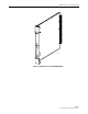
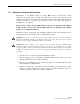
ADCP-61-743 • Issue 3 • September 2004 1 DESCRIPTION The Remote Test Access Unit (RTAU) (Figure 1) provides maintenance functionality for monitoring and intrusive test access to the DS1 channels in the chassis between the DS3 MUX and the low speed distribution modules (DLX, HLXC, ODS2, and RLX). The RTAU requires no periodic maintenance. It requires the Version D1 or later DS3 MUX module and MPU Version 5.3 or SCU Version 3.
ADCP-61-743 • Issue 3 • September 2004 RTAU STAT US B8ZS AMI LINE CODE INTRU SI TEST VE BIPOLA ACCE R SS D S 1 11897-A RX TX Figure 1. Remote Test Access Unit (RTAU) Module Page 5 © 2004, ADC Telecommunications, Inc.
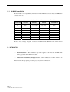
ADCP-61-743 • Issue 3 • September 2004 1.1 DS3 MUX Compatibility Refer to Table 1 for compatibility information for DS3 MUXs, test access units, and MPU/SCU software versions. Table 1. DS3 MUX, TAU/RTAU, and MPU/SCU Software Compatibility DS3 MUX TYPE TEST ACCESS UNIT TYPE MPU SOFTWARE VERSION SCU SOFTWARE VERSION FUNCTIONALITY C1 TAU 5.1.1 or later 2.5 or later TAU C1 RTAU 5.1.1 or later 2.0 or later NO TEST ACCESS D1 TAU 5.1.1 or later 2.5 or later TAU D1 RTAU 5.2 or earlier 2.
ADCP-61-743 • Issue 3 • September 2004 2.1 Initial Installation This installation procedure applies to the first time an IBBC shelf will be populated with a RTAU module. If the IBBC shelf has already been populated with a RTAU module, go to 2.2. Maintenance Installation (Existing System). Installation consists of unpacking and installing the RTAU module, and verifying that it is functioning properly.
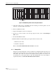
ADCP-61-743 • Issue 3 • September 2004 HSW HSP MXW MXP TAU 1-1 1-3 2-1 2-3 3-1 3-3 4-1 4-3 5-1 5-3 6-1 6-3 7-1 7-3 APU CR MJ MN ACO PWR RTAU HSKP RMT ALM STATUS STATUS DISP RMT LPBK LPBK ENABLE ENABLE ONLINE ONLINE DS3 FAIL DS3 FAIL STATUS LMPTST B8ZS AMI APU LINE CODE INTRUSIVE TEST STATUS LOCKOUT LOCKOUT APS APS FORCE C FORCE R A LMPTST/ APS LMPTST/ APS RESET RESET F RX T D S 1 TX RESET 1-2 1-4 2-2 2-4 3-2 3-4 4-2 4-4 5-2 5-4 6-2 6-4 7-2
ADCP-61-743 • Issue 3 • September 2004 2.2 Maintenance Installation (Existing System) Replacement of the RTAU module in existing IBBC shelves should follow normal maintenance procedures. Since a module has already been in service in the affected slot, the backplane pins will have been trained into alignment with subsequent replacement modules. If excessive resistance is encountered upon insertion, remove the module and inspect for misalignment or obstructions.
ADCP-61-743 • Issue 3 • September 2004 3 LED CHECK 1. When the RTAU module (Figure 3) is seated, the STATUS LED will be lit red for approximately 5 seconds. All LEDs will then flash yellow, and then the STATUS LED will be lit green. If the STATUS LED is not lit green after 10 seconds, replace the module. Refer to 2.2 Maintenance Installation (Existing System). RTAU STATUS B8ZS AMI LINE CODE INTRUSIVE TEST BIPOLAR ACCESS D S 1 RX TX 12693-B Figure 3.
ADCP-61-743 • Issue 3 • September 2004 4 FRONT PANEL OPERATION All controls and indicators of the RTAU including the jack accesses for a selected DS1 signal are located on the front panel (Figure 3). The controls and indicators are described in Table 2. Table 2. RTAU Front Panel Description INDICATOR COLOR STATUS Red B8ZS / AMI Module failure. Yellow LED test. Green Module operating normally. Green Indicates that the user has selected B8ZS line code for the bipolar interface.
ADCP-61-743 • Issue 3 • September 2004 5 CONFIGURATION Use this menu to view or edit the configuration for the RTAU module after it is installed in the chassis. This menu can also be used to equip, provision, assign thresholds, and assign service state. Note: A “toggle” field type means the user can press the space bar to view and select the next option that is described; or the user can press the “R” key to view and select the previous option.
ADCP-61-743 • Issue 3 • September 2004 5. Use the arrow or number keys to select RTAU Setup and Control from the RTAU Configuration menu. Press Enter or Return. The RTAU Setup and Control screen will appear as shown in Figure 6. Note: If the RTAU is not plugged into the chassis and the Test Access Unit Commands selection is made from the System Maintenance menu, the Test Access Unit Status/Commands screen will appear as shown in Figure 7. This screen cannot be configured.
ADCP-61-743 • Issue 3 • September 2004 SYSTEM MAINTENANCE 1. 2. 3. 4. 5. 6. 7. 8. 9. A. Force/APS Commands Reset/LED Test Commands Execute ACO (Alarm Cutoff) Loopback Status/Commands Display Inventory Display Circuit IDs SCU-860 Data Transfer Commands Trouble Isolation Metallic Testing Screen (for IBBCMLQ only) Test Access Unit Commands Press CONTROL-A For Assistance Figure 4. System Maintenance Menu RTAU CONFIGURATION 1. RTAU Setup and Control 2.
ADCP-61-743 • Issue 3 • September 2004 7. Assign the selections by pressing Enter or Return.
ADCP-61-743 • Issue 3 • September 2004 Table 3. RTAU Configuration Fields FIELD TYPE OPTIONS DESCRIPTION DEFAULT OVERVIEW: The Current User field can only be set to NONE or CRAFT from the Craft menu. If the Current User field is set to NONE, the Mode field is automatically set to DISABLE. However, to change this field to CRAFT, the Mode field must first be set to an option other than DISABLE. At that point, the Current User field is automatically set to CRAFT.
ADCP-61-743 • Issue 3 • September 2004 Table 3.
ADCP-61-743 • Issue 3 • September 2004 Table 3. RTAU Configuration Fields, continued FIELD TYPE OPTIONS DESCRIPTION DEFAULT EQUIPMENT SETUP FIELDS, continued Mode, continued Toggle SPLTEL SPLTEL indicates a split in both the A and B paths and connects an SPD to the line incoming from the E direction and a TSG to the line outgoing in the E direction similar to SPLTE mode. The signal in the F direction is looped back.
ADCP-61-743 • Issue 3 • September 2004 Table 3. RTAU Configuration Fields, continued FIELD TYPE OPTIONS DESCRIPTION DEFAULT SIGNAL GENERATOR SETUP FIELDS, CONTINUED Pattern Type, continued Toggle 2^15-1 215-1 is a 32,767-bit, pseudo-random pattern that generates a maximum of 14 sequential 0’s and 15 sequential 1’s. The pattern provides a maximum number of 0’s allowed for framed, non-B8ZS testing. The pattern does not meet the minimum 1’s density requirement.
ADCP-61-743 • Issue 3 • September 2004 Table 3. RTAU Configuration Fields, continued FIELD TYPE OPTIONS DESCRIPTION DEFAULT SIGNAL GENERATOR SETUP FIELDS, continued Pattern Type, continued Toggle 1 in 8 Containing strings of 7 sequential 0’s. It is used to determine the ability of a circuit to handle payload signals having minimum 1’s density. Use of this pattern often reveals the existence of timing recovery problem under conditions of low signal density.
ADCP-61-743 • Issue 3 • September 2004 Table 3. RTAU Configuration Fields, continued FIELD TYPE OPTIONS DESCRIPTION DEFAULT OVERVIEW: The Mode field must be set to a SPLT option before the Loop Code field can be configured. Loop codes will be transmitted until the RTAU detects a change in the signal being received. At that time, the pattern selected before the loop code was set will be transmitted.
ADCP-61-743 • Issue 3 • September 2004 Table 3. RTAU Configuration Fields, continued FIELD TYPE OPTIONS DESCRIPTION DEFAULT BIT ERROR SETUP FIELDS OVERVIEW: Bit errors can be injected by the RTAU using the Bit Error Set Up fields. These sections are display-only fields that are only displayed when the line code setting is INTERNAL.
ADCP-61-743 • Issue 3 • September 2004 Table 3. RTAU Configuration Fields, continued FIELD TYPE OPTIONS DESCRIPTION DEFAULT Elapsed Time ES Display only None Six-digit counter or blank. Blank Elapsed Time EFS Display only None Six-digit counter or blank. Blank 0 to 1440 Timeout counter for test access. If the counter is set to a number higher than “0” and then reaches “0” during test, the Mode field will be set to DISABLE automatically.
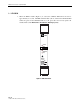
ADCP-61-743 • Issue 3 • September 2004 DS3 MUX MPU or SCU RTAU BIPOLAR ACCESS RTAU FRONT PANEL RX PATTERN GEN DETECTOR DS3 EQUIPMENT DS1 TEST SET TX LINE CARD CONTROLLER A B DS1 FACILITY MONITOR SPLIT 11864-C Figure 8. RTAU Test Configuration Block Diagram EQUIPMENT (E) [NETWORK] A FACILITY (F) [CUSTOMER] DS3 MUX EQUIPMENT (E) [NETWORK] A B B CIRCUIT UNDER TEST B RTAU CIRCUIT UNDER TEST MONF MONE SIGNAL PRESENCE DETECTOR SIGNAL PRESENCE DETECTOR Figure 9.
ADCP-61-743 • Issue 3 • September 2004 EQUIPMENT (E) [NETWORK] FACILITY (F) [CUSTOMER] EQUIPMENT (E) [NETWORK] CIRCUIT UNDER TEST CIRCUIT UNDER TEST SPLTB SPLTA SIGNAL PRESENCE DETECTOR SIGNAL PRESENCE DETECTOR TEST SIGNAL GENERATOR TEST SIGNAL GENERATOR DS3 MUX A B RTAU FACILITY (F) [CUSTOMER] DS3 MUX A B RTAU 11866-B Figure 10.
ADCP-61-743 • Issue 3 • September 2004 INTEROFFICE FACILITY OFFICE A A END RTAU A F OFFICE Z E E A Z END F INSERT: NETWORK DROP: NETWORK LOOPBACK B B CPE CPE QRS SPLTE A = "A" TRANSMISSION PATH B = "B" TRANSMISSION PATH E = EQUIPMENT (NETWORK) F = FACILITY (CUSTOMER) = SIGNAL PRESENCE DETECTOR 11868-B = TEST SIGNAL GENERATOR OR UNFRAMED (QRS) = TERMINATED SIGNAL Figure 12.
ADCP-61-743 • Issue 3 • September 2004 INTEROFFICE FACILITY OFFICE A A END RTAU F INSERT: NETWORK A B OFFICE Z E E DROP: CUSTOMER DROP: NETWORK INSERT: CUSTOMER INSERT: NETWORK Z END RTAU A F INSERT: CUSTOMER B CPE CPE QRS QRS SPLTF SPLTE A = "A" TRANSMISSION PATH B = "B" TRANSMISSION PATH E = EQUIPMENT (NETWORK) F = FACILITY (CUSTOMER) = SIGNAL PRESENCE DETECTOR = TEST SIGNAL GENERATOR OR UNFRAMED (QRS) = TERMINATED SIGNAL 11870-B Figure 14.
ADCP-61-743 • Issue 3 • September 2004 EQUIPMENT (E) [NETWORK] DS3 MUX QRS FACILITY (F) [CUSTOMER] EQUIPMENT (E) [NETWORK] A A B B CIRCUIT UNDER TEST CIRCUIT UNDER TEST LOOPF LOOPE SIGNAL PRESENCE DETECTOR SIGNAL PRESENCE DETECTOR RTAU DS3 MUX FACILITY (F) [CUSTOMER] QRS RTAU 11872-B Figure 16.
ADCP-61-743 • Issue 3 • September 2004 Table 4.
ADCP-61-743 • Issue 3 • September 2004 8 CUSTOMER INFORMATION AND ASSISTANCE ADC Technical support is available 24 hours a day, 7 days a week by contacting the ADC Technical Assistance Center. Sales Assistance 800.366.3891 • Quotation Proposals • Ordering and Delivery • General Product Information Systems Integration 800.366.