ADCP-50-304 Issue 19 June 1999 RS-232/V.24, X.21 and V.
ADCP-50-304 • Issue 19 • June 1999 • Preface COPYRIGHT © 1999, ADC Telecommunications, Inc. All Rights Reserved Printed in the U.S.A. TRADEMARK INFORMATION ADC and ADC Telecommunications are registered trademarks of ADC Telecommunications, Inc. DISCLAIMER OF LIABILITY Contents herein are current as of the date of publication. ADC reserves the right to change the contents without prior notice.
ADCP-50-304 • Issue 19 • June 1999 • Preface TABLE OF CONTENTS Content Page SECTION 1 INTRODUCTION 1 GENERAL. . . . . . . . . . . . . . . . . . . . . . . . . . . . . . . . . . . . . . . . . . . . . . . . . . . . . . . . . . . . . . . . . . . . . . . . . . . . . . . . . . . . . . . . . . . . . . . . . 1-1 2 PURPOSE AND SCOPE . . . . . . . . . . . . . . . . . . . . . . . . . . . . . . . . . . . . . . . . . . . . . . . . . . . . . . . . . . . . . . . . . . . . . . . . . . . . . . . . . . . . . 1-2 3 2.
ADCP-50-304 • Issue 19 • June 1999 • Preface TABLE OF CONTENTS Content Page SECTION 4 PATCHSWITCH X.21 1 GENERAL. . . . . . . . . . . . . . . . . . . . . . . . . . . . . . . . . . . . . . . . . . . . . . . . . . . . . . . . . . . . . . . . . . . . . . . . . . . . . . . . . . . . . . . . . . . . . . . . . 4-1 2 DESCRIPTION . . . . . . . . . . . . . . . . . . . . . . . . . . . . . . . . . . . . . . . . . . . . . . . . . . . . . . . . . . . . . . . . . . . . . . . . . . . . . . . . . . . . . . . . . . .
ADCP-50-304 • Issue 19 • June 1999 • Preface TABLE OF CONTENTS Content Page SECTION 6 INSTALLATION 1 GENERAL. . . . . . . . . . . . . . . . . . . . . . . . . . . . . . . . . . . . . . . . . . . . . . . . . . . . . . . . . . . . . . . . . . . . . . . . . . . . . . . . . . . . . . . . . . . . . . . . . 6-1 1.1 PatchSwitch Chassis Installation (For PatchSwitch V.35 Installation, see Section 3) . . . . . . . . . . . . . . . . . . . . . . . . . . . 6-1 1.2 PatchSwitch Module Installation Procedure . . . .
ADCP-50-304 • Issue 19 • June 1999 • Preface TABLE OF CONTENTS Content Page 6.15 Request Software Revision Level (REV) Command) . . . . . . . . . . . . . . . . . . . . . . . . . . . . . . . . . . . . . . . . . . . . . . . . . . . . . 7-10 6.16 Request Status (UPdate Command). . . . . . . . . . . . . . . . . . . . . . . . . . . . . . . . . . . . . . . . . . . . . . . . . . . . . . . . . . . . . . . . . . . 7-10 6.17 Status Responses . . . . . . . . . . . . . . . . . . . . . . . . . . . . . . . . . .
ADCP-50-304 • Issue 19 • June 1999 • Preface REVISION HISTORY EDITION/ISSUE DATE REASON FOR CHANGE 1st Edition, Issue 1 02/83 Original. 1st Edition, Issue 2 03/83 Technical changes. 1st Edition, Issue 3 03/83 Warranty changes. 1st Edition, Issue 4 07/83 Technical changes. 2nd Edition, Issue 1 02/84 Incorporation of remote control. 2nd Edition, Issue 2 10/84 Technical changes. 3rd Edition, Issue 1 03/86 Incorporated PSM-12 and PSM-13 Test Modules.
ADCP-50-304 • Issue 19 • June 1999 • Preface RELATED PUBLICATIONS Listed below are all the related manuals, their content, and their publication numbers. Copies of these publications can be ordered by contacting the ADC Technical Assistance Center at 1-800-366-3891 (in U.S.A. or Canada) or 612-946-3000, extension 3223 (outside U.S.A. and Canada. Title Network Control Products Catalog ADCP Number 517 PatchSwitch Remote Control Unit User Manual ADCP-50-302 PatchSwitch V.
ADCP-50-304 • Issue 19 • June 1999 • Preface GENERAL SAFETY PRECAUTIONS Danger: To prevent electrical shock, never install telephone equipment in a wet location or during a lightning storm. When installing or modifying telephone lines, disconnect lines on the network side before working with uninsulated lines or terminals. Danger: The chassis must be properly grounded to ensure equipment and human safety. Danger: Electric modules can be damaged by electrostatic discharge (ESD).
INTRODUCTION
ADCP-50-304 • Issue 19 • June 1999 • Section 1: Introduction SECTION 1: INTRODUCTION Content Page 1 GENERAL . . . . . . . . . . . . . . . . . . . . . . . . . . . . . . . . . . . . . . . . . . . . . . . . . . . . . . . . . . . . . . . . . . . . . . . . . . . .1-1 2 PURPOSE AND SCOPE . . . . . . . . . . . . . . . . . . . . . . . . . . . . . . . . . . . . . . . . . . . . . . . . . . . . . . . . . . . . . . . . . . .1-2 3 2.1 PatchSwitch Assembly Configurations . . . . . . . . . . . . . . . . . . . . .
ADCP-50-304 • Issue 19 • June 1999 • Section 1: Introduction 12. Remote switching and alarm control operation up to 1,000 feet away from the PatchSwitch chassis rack; 13. Remote operator control via serial data communications circuits employing either RS-232, RS-422 or V.35 standards; 14. Optional autofallback to either A/B switch position on detection of an alarm; 15. Local or remote bank switching using manual or serial control; 16. 0, +5V and –5 to –48 Vdc pulse controlled bank switching, and 17.
ADCP-50-304 • Issue 19 • June 1999 • Section 1: Introduction The Interlocked group feature protects a device used as a substitute. A spare device may be connected to the DTE-B port of several A/B switching modules as shown in Figure 1-1. The A/B Interlock Jumper of each module in the group must be in the same position. When one device fails, the spare device may be substituted.
ADCP-50-304 • Issue 19 • June 1999 • Section 1: Introduction MODULE 1 A MODEM 1 B MODULE 2 A MODEM 2 B MODULE 3 A MODEM 3 B MODULE 4 A B MODEM 4 SPARE MODEM FRONT END PROCESSOR 1588-A Figure 1-1. Typical Hot Spare Modem Configuration Page 1-4 © 1999, ADC Telecommunications, Inc.
ADCP-50-304 • Issue 19 • June 1999 • Section 1: Introduction 2.2 PatchSwitch Equipment The PS equipment consists of a chassis with a control module and associated power supply, modules forpatching and/or switching and interfacing, blank panel and patch cords. Table 1-2 lists the PS equipment. Table 1-2. PatchSwitch Equipment (V.35 Modules are described in Section 3. X.
ADCP-50-304 • Issue 19 • June 1999 • Section 1: Introduction Table 1-2. PatchSwitch Equipment, continued (V.35 Modules are described in Section 3. X.21 Modules are described in Section 4) ADC NUMBER DESCRIPTION COMMENTS PSW-000002 PatchSwitch Power Supply (9 pin in-line connector) Dual output supply used with RDC-01/RDC-02 chassis with input power source –48 Vdc.
ADCP-50-304 • Issue 19 • June 1999 • Section 1: Introduction 2.2.3 Data Converter Module (PSR-06) This module is a printed circuit board assembly with components, a front panel with four LED status indicators and a rear 96-pin DIN connector. The module interfaces with the ADC Remote Control Unit, a user's CRT terminal, or computer, and converts signals providing RS-422/RS232 compatibility to permit remote serial control for PatchSwitch equipment to be connected to RS-232 modem or CRTs. 2.2.
ADCP-50-304 • Issue 19 • June 1999 • Section 1: Introduction 2.2.11 Blank Panel (PSM-09) This panel is used in chassis module positions in lieu of a module. The panel is a two piece assembly secured to the chassis by two mounting screws. 2.2.12 Test Module (PSM-12) Test Module PSM-12 is normally mounted in the slot position 17 of the PS chassis, but may be mounted in any slot to the left of position 17 (1 through 16). This module provide the user with RS-232/V.
ADCP-50-304 • Issue 19 • June 1999 • Section 1: Introduction 3 SPECIFICATIONS Physical Characteristics PS Chassis Height: Width: Depth: 7 inches 19 inches 12 inches (17.78 cm) (48.3 cm) (30.12 cm) Environmental Conditions Ambient Temperature: Operating: +32° F to +122° F (0° C to +50° C) Storage: –40° F to +158° F (–40° C to +70° C) Relative Humidity: Operating: 10% to 80% noncondensing Storage: 5% to 90% noncondensing Power Requirements PS Chassis: +5 Vdc @ 3 amps +12 Vdc @ 1 amp (switching) 3.
FUNCTIONAL DESCRIPTION
ADCP-50-304 • Issue 19 • June 1999 • Section 2: Functional Description SECTION 2: FUNCTIONAL DESCRIPTION Content Page 1 GENERAL . . . . . . . . . . . . . . . . . . . . . . . . . . . . . . . . . . . . . . . . . . . . . . . . . . . . . . . . . . . . . . . . . . . . . . . . . . . .2-1 2 PATCHING WITH IN-LINE A/B SWITCHING . . . . . . . . . . . . . . . . . . . . . . . . . . . . . . . . . . . . . . . . . . . . . . . . . . . . . .2-1 3 A/B SWITCHING WITH OFF-LINE MONITOR ACCESS . . . . . . . . . . . . . .
ADCP-50-304 • Issue 19 • June 1999 • Section 2: Functional Description FRONT PANEL CONNECTIONS BACKPLANE CONNECTIONS J1 DTE-A A COMPUTER B J2 DTE-B MODEM J3 DCE LED/ALARM ELECTRONICS (PSM-01 ONLY) 1607-A MONITOR Figure 2-1. PatchSwitch with In-Line Access (PSM-01, PSM-02) 3 A/B SWITCHING WITH OFF-LINE MONITOR ACCESS The capability for accessing the off-line DTE device is illustrated in Figure 2-2.
ADCP-50-304 • Issue 19 • June 1999 • Section 2: Functional Description FRONT PANEL CONNECTIONS A BACKPLANE CONNECTIONS B A J1 DTE-A A B J2 DTE-B B LED/ALARM ELECTRONICS (PSM-04 ONLY) J3 DCE C 1608-A Figure 2-2. PatchSwitch with Off-Line Access (PSM-04, PSM-05) 3.1 PS Control Module (RDM-15) The PS Control Module (CM) controls the overall manual operations of the modules contained in the PS chassis. Three toggle switches located on the front panel have the following functions: 1.
ADCP-50-304 • Issue 19 • June 1999 • Section 2: Functional Description A remote control device can control the operation of up to 16 full PS chassis assemblies (16 modules each) using a dedicated communications channel. This channel has four signals: 1. Transmit Data (TD) 2. Receive Data (RD) 3. Clear-To-Send (CTS) 4. Request-To-Send (CTS) Each of the above signals has the same function as the corresponding signals defined by the RS232 standard.
ADCP-50-304 • Issue 19 • June 1999 • Section 2: Functional Description UP TO 1000 FT. (304 M) PATCHSWITCH CHASSIS 0 REMOTE CONTROL UNIT CM 0 SLOT 18 RS-422 RS-232 RS-422 COMMUNICATION CHANNEL B A C K P L A N E SLOT 17 PS MODULE SLOT 16 SLOTS 2 – 15 PS MODULE SLOT 1 RS-422 COMMUNICATION CHANNEL PS CHASSIS 1 PS CHASSIS 2–5 PS CHASSIS 6 RS-422 COMMUNICATION CHANNEL PATCHSWITCH CHASSIS 7 CM 7 SLOT 18 B A C K P L A N E SLOT 17 PS MODULE SLOT 16 SLOTS 2 – 15 PS MODULE SLOT 1 1610-A Figure 2-4.
ADCP-50-304 • Issue 19 • June 1999 • Section 2: Functional Description The cable connectors are 9-pin, D-subminiature. Both end-connectors are male. The cable may be up to 1,000 feet in length. Connector pin assignments are detailed in Table 2-1. Table 2-1.
ADCP-50-304 • Issue 19 • June 1999 • Section 2: Functional Description Table 2-2. DB-9 Pinout and Signal Characteristics PIN OULTAGE INPUT CHANNEL (SWITCHED TO) 1 Chassis Ground N/A 2 –48V +5% (–5V min) B 3 +5V +5% B 4 Remote Ground In B 5 Signal Return 6 –48V +5% (–5V min) A 7 5V +5% A 8 Remote Ground In A 9 Signal Return N/A N/A Note: The dc voltages indicated in Table 2-2 must be present for a minimum of 250 msec to ensure switching.
ADCP-50-304 • Issue 19 • June 1999 • Section 2: Functional Description The three classes of interlock groups available are: 1. Global Interlock: Groups 1 and 2 are global and may be extended to all chassis in a system, using a 20-pin interchassis interlock cable. With this grouping, all modules having a jumper placed on group 1 make up one group, and all modules with a jumper on group 2 make up the other group. Interchassis interlock cables must be installed between chassis.
ADCP-50-304 • Issue 19 • June 1999 • Section 2: Functional Description A/B RELAYS A/B SWITCH INDICATORS A/B DTE AND ALARM LOGIC A/B RELAY COMPUTER DTE (A) MODEM DTE (B) MONITOR DCE UPPER INTERFACE PORT LOWER INTERFACE PORT 1641-A Figure 2-5.
ADCP-50-304 • Issue 19 • June 1999 • Section 2: Functional Description Table 2-3.
ADCP-50-304 • Issue 19 • June 1999 • Section 2: Functional Description Table 2-4. LED Status Indicators LED STATUS INDICATOR COLOR SIGNAL DEFINITION A Red DTE-A B Green DTE-B TD Green Transmitted Data RD Green Received Data DCD Green Data Carrier Detect SQ Green Signal Quality Detect RTS Red Request To Send CTS Red Clear To Send DSR Red Data Set Ready DTR Red Data Terminal Ready ALM Yellow Alarm On Table 2-5.
ADCP-50-304 • Issue 19 • June 1999 • Section 2: Functional Description 4 A/B SWITCHING MODULE (PSM-03) This module provides A/B switching only. A simplified circuit diagram of this module is shown in Figure 2-8. The A/B switch activates the A/B relays. The A/B relays complete the channel between the DCE and either DTE-A or DTE-B. The relays also switch in the interlock jumper.
ADCP-50-304 • Issue 19 • June 1999 • Section 2: Functional Description A/B SWITCH CONTROL A TOGGLE SWITCH B A/B SWITCH LOGIC CONTROL MODULE A/B RELAYS A/B INTERLOCK JUMPER GROUP 1 A B A/B RELAYS 2 3 4 TO CHASSIS BACKPLANE V VERTICAL INTERLOCK A/B RELAY DTE (A) UPPER INTERFACE PORT DTE (B) DCE LOWER INTERFACE PORT 1613-A Figure 2-8.
ADCP-50-304 • Issue 19 • June 1999 • Section 2: Functional Description alarm is thus user selectable for any one of eight leads of the lower patch port. The EIA RS-232/ CCITT V.24 modem interface signal leads are shown in Table 2-3. The alarm circuit control logic supplies the alarm signal to the control module and an alarm indicator.
ADCP-50-304 • Issue 19 • June 1999 • Section 2: Functional Description ALARM JUMPER TD PIN 2 RD PIN 3 PIN 8 DCD STATUS INDICATORS SQ PIN 21 RTS DSR PIN 4 PIN 5 PIN 6 DTR PIN 20 CTS ALARM INDICATOR TOUCH SWITCH TOGGLE SWITCH ROTARY SWITCH LOWER INTERFACE RS-232C LEADS PIN 7 ALM RST OFF ALM LED ALARM CIRCUIT CONTROL LOGIC AUTOMATIC ALARM RESET DLY CONTROL MODULE ALARM +5 Vcd GND BACKPLANE STORE 1615-A Figure 2-10.
ADCP-50-304 • Issue 19 • June 1999 • Section 2: Functional Description This logic is also controlled by the RST (Reset) touch switch, toggle switch OFF (LED off, audible alarm off), ALM (LED and audible alarm on), LED (LED on, audible alarm off), and rotary switch DLY (alarm time delay setting). The alarm may be automatically reset if the automatic alarm reset jumper is in place. Alarm delay settings are shown in Table 2-5.
ADCP-50-304 • Issue 19 • June 1999 • Section 2: Functional Description 10 PS RS-422/RS-232 INTERFACE CONVERTER MODULE (PSR-06) The PatchSwitch module converts signals to provide RS-422/RS-232 compatibility for remotely controlled PatchSwitch equipment, see Figure 2-13. Mounted in slot position 17 of the PatchSwitch chassis, the Data Converter Module interfaces with the ADC Remote Control Unit, CRT terminal, or computer directly, or indirectly through modems and telephone lines.
ADCP-50-304 • Issue 19 • June 1999 • Section 2: Functional Description CHASSIS BACKPLANE CONNECTIONS L E D R S 2 3 2 LEVEL 1 CONVERTER UPPER 25-PIN "D" SUB TO/FROM RCU OR TERMINAL (F) DTE/DCE SELECTOR 9-PIN "D" SUBS TO/FROM OTHER CHASSIS RDMS OR RDCS SLOT POSITION 17 1560-A Figure 2-14. PSR-06 Interface Converter 11 PS CHASSIS POWER A power supply unit is used with the PS Chassis. The PSW-000001 or PSW-000003 is used when input power is 90 to 240 VAC.
PATCHSWITCH V.
ADCP-50-304 • Issue 19 • June 1999 • Section 3: PatchSwitch V.35 SECTION 3: PATCHSWITCH V.35 Content Page 1 PRODUCT OFFERING . . . . . . . . . . . . . . . . . . . . . . . . . . . . . . . . . . . . . . . . . . . . . . . . . . . . . . . . . . . . . . . . . . . .3-1 2 APPLICATION WITH EXISTING UNITS . . . . . . . . . . . . . . . . . . . . . . . . . . . . . . . . . . . . . . . . . . . . . . . . . . . . . . . . .3-2 3 FUNCTION SELECTION-MODULES . . . . . . . . . . . . . . . . . . . . . . . . . . . . . .
ADCP-50-304 • Issue 19 • June 1999 • Section 3: PatchSwitch V.35 2 APPLICATION WITH EXISTING UNITS The V.35 PatchSwitch modules can be identified by their gray color. A conversion board must be installed onto the chassis, as shown in Figure 3-1 and Figure 3-2, before the V.35 module assembly is placed into service. If the conversion boards are not practical, user cables can be manufactured by local sources to terminate the standard V.
ADCP-50-304 • Issue 19 • June 1999 • Section 3: PatchSwitch V.35 BACKPLANE V.35 PATCH MODULE STATUS, DELAY, AND ALARM CIRCUITS A FEMALE A FEMALE C C REAR BOARD FRONT LOADING BOARD 1624-A Figure 3-2. V.35 Interface Module and Conversion Board Table 3-2. Normal Pin Assignments ORIGIN SIGNAL DESCRIPTION DB-25 CONNECTOR PIN V.
ADCP-50-304 • Issue 19 • June 1999 • Section 3: PatchSwitch V.35 Table 3-2. Normal Pin Assignments, continued ORIGIN SIGNAL DESCRIPTION DB-25 CONNECTOR PIN RC (+) DCE Rec Clck (+) 17 X RC (–) DCE Rec Clck (–) 18 Y TC (+) DCE Trans Clck (+) 15 AA TC (–) DCE Trans Clck (–) 16 MM BSY DCE Busy Signal 25 V.
ADCP-50-304 • Issue 19 • June 1999 • Section 3: PatchSwitch V.35 ITEM B DS1 TD RD RTS CTS DCD TC RC DTR DS2 E44 E42 E40 E38 E14 E16 E18 E20 LCHD E22 E24 LCHD E26 E28 E34 E36 P1 ALM + ALM – 1 Y U AA W E30 E32 22 ITEM A 1625-A ITEM C ITEM D Figure 3-3. PSM-16 and PSM-17 Module PC Board (Component Side) 4 FUNCTIONAL SELECTION—CONVERSION BOARD The item found in Table 3-4 is associated with the conversion board. Refer to Figure 3-4 or Figure 3-5 for item locations.
ADCP-50-304 • Issue 19 • June 1999 • Section 3: PatchSwitch V.35 CC KK NN JJ DD Z N L E2 E3 E4 E5 E6 E7 CC KK NN JJ DD Z N L E2 E3 E4 E5 E6 E7 EE HH LL FF BB M K EE HH LL FF BB M K TABLE 3-4 AND 3-5 V.35 THREE MALES E7 E6 E5 E4 E3 E2 L N Z DD JJ NN KK CC K M BB FF LL HH EE 1626-A Figure 3-4. FFM-01 and FFM-02 Conversion Board CC KK NN JJ DD Z N L E2 E3 E4 E5 E6 E7 V.
ADCP-50-304 • Issue 19 • June 1999 • Section 3: PatchSwitch V.35 Table 3-5. Connections of Unassigned Pins on Subboard o---K o---L o---M o---N oE2 o---Z oE3 o---BB oE4 o---CC oE5 o---DD oE6 o---EE oE7 o---FF o---HH o---JJ o---KK o---LL o---NN The Pin pattern and identification is as noted above for the fifteen (15) leads unused from the V.35 connector and the six (6) leads unused through the patching function.
ADCP-50-304 • Issue 19 • June 1999 • Section 3: PatchSwitch V.35 5 HARDWARE INSTALLATION Remove power to the shelf by turning off the power supply or unplugging the power transformer connected to the chassis. If proceeding with an upgrade of a current installation it may be necessary to remove any cable wrap, clamps or cord form any existing cable brackets to allow room for installation of the conversion boards. Be careful not to damage cables or connectors in the process.
ADCP-50-304 • Issue 19 • June 1999 • Section 3: PatchSwitch V.35 6 RECOMMENDED MATING CONNECTOR PARTS DESCRIPTION VENDOR PART NUMBER Connector V.35 (Female) WINCHESTER POSITRONICS MRAC MS 34S VMCT-34F-000000-538-Z Contacts (Female) WINCHESTER POSITRONICS 100-51024S FC 124N2 Hood WINCHESTER POSITRONICS MRE34JTDH G34-00000-40 Connector V.35 (Male) AMP INC 201357-1 Contacts (Male) AMP INC 66703-2 Note: The hold down screws on the cable plugs for the ADC V.
PATCHSWITCH X.
ADCP-50-304 • Issue 19 • June 1999 • Section 4: PatchSwitch X.21 SECTION 4: PATCHSWITCH X.21 Content Page 1 GENERAL . . . . . . . . . . . . . . . . . . . . . . . . . . . . . . . . . . . . . . . . . . . . . . . . . . . . . . . . . . . . . . . . . . . . . . . . . . . .4-1 2 DESCRIPTION . . . . . . . . . . . . . . . . . . . . . . . . . . . . . . . . . . . . . . . . . . . . . . . . . . . . . . . . . . . . . . . . . . . . . . . . .4-2 3 2.1 PSM-812001 X.
ADCP-50-304 • Issue 19 • June 1999 • Section 4: PatchSwitch X.21 2 DESCRIPTION The ADC PatchSwitch X.21 modules provide monitor and patch access to X.21 leads. Some modules also provide local and remote alarming, testing, or status indicators. 2.1 PSM-812001 X.21 LED/Alarm Patch Module with A/B Switching and Off-Line Patch Access This module provides monitoring and access to 15 active X.21 leads, A/B Switching, LED signal status indication, and call request and termination time-out alarming.
ADCP-50-304 • Issue 19 • June 1999 • Section 4: PatchSwitch X.21 2.2 PSM-813001 X.21 PatchSwitch Module with A/B Switching and Off-Line Patch Access This module provides monitoring and access to 15 active X.21 leads and A/B/ Switching. A Block diagram representing the PSM-813001 module is shown in Figure 4-2. SWITCHING CIRCUIT 1629-A Figure 4-2. PSM-813001 Module Block Diagram 2.3 PSM-832001 X.21 LED/Alarm PatchSwitch Interface Module This Module provides monitoring and access to 15 active X.
ADCP-50-304 • Issue 19 • June 1999 • Section 4: PatchSwitch X.21 2.4 PSM-83301 X.21 PatchSwitch Module This module provides monitoring and access to 15 active X.21 leads. A block diagram representing the PSM-833001 module is shown in Figure 4-4. 1631-A Figure 4-4. PSM-833001 Module Block Diagram 2.5 PSM-832002 X.21 LED/Alarm PatchSwitch Test/Status Module This module provides monitoring and access to 15 active X.21 leads through a standard patch port.
ADCP-50-304 • Issue 19 • June 1999 • Section 4: PatchSwitch X.21 2.6 PSO-839001 Backplane Adapter Module Three 15-pin D-sub connectors, located on the back of this backplane adapter provide a point of connection for customer cabling. The top two rear connectors are female and the bottom one is male. Three male 25 pin D-sub connectors on the front of the backplane adapter provide connections to the RDC-01/PSC-01 PatchSwitch chassis backplane. 2.
ADCP-50-304 • Issue 19 • June 1999 • Section 4: PatchSwitch X.21 A/B SWITCHING MODULE CHASSIS BACKPLANE BACKPLANE ADAPTER SWITCHING CIRCUIT ALARM CIRCUITS PATCH X.21 A A A B B B C C 1633-A Figure 4-6. A/B Switching Block Diagram 3.2 Switch Module Interlocks The A/B switch activates the A/B relays. The A/B relays complete the X.21 circuit between the DCE and either the DTE-A or DTE-B. The relays also switch in the interlock group. A and B status indicators show the DTE-A and DTE-B selection.
ADCP-50-304 • Issue 19 • June 1999 • Section 4: PatchSwitch X.21 3.4 Status Indication Modules The six X.21 circuit leads having LED indicators are: T, C, R, I, S, and B. When a monitored circuit lead is active (signal present), the associated LED indicator turns on only while the signal is present. The colors and signal definitions for the applicable Led Status indicators shown in Table 4-1. Table 4-1. Signal Status ABBREVIATION 3.
ADCP-50-304 • Issue 19 • June 1999 • Section 4: PatchSwitch X.21 3.7 Alarm Time Delay The PSM-832002 Test/Status module contains two eight position rotary switches on the front panel. One for the A alarm delay and one for the B alarm delay. All other modules contain one eight position rotary switch on the front panel. This switch is used to set the B alarm delay. The A alarm time delay is set using a 16 position rotary switch located on the PC board. Time delay values are fixed.
ADCP-50-304 • Issue 19 • June 1999 • Section 4: PatchSwitch X.21 Table 4-3. B Alarm Time Delay Settings ARC LENGTH SWITCH POSITION TIME DELAY V 0 None Shortest 1 55 msec 2 117 msec 3 242 msec 4 492 msec 5 992 msec 6 1.9 sec 7 3.9 sec Longest 3.8 B Alarm Enable/Disable The alarm can be disabled by moving the jumper labeled ALMB/ALMB on the module board. The alarm is enabled when the jumper is in the ALMB position. The alarm is disabled when the jumper is in the ALMB position. 3.
ADCP-50-304 • Issue 19 • June 1999 • Section 4: PatchSwitch X.21 5 SPECIFICATIONS Module specification are shown in Table 4-5. Table 4-5. Specifications PARAMETER SPECIFICATIONS REMARKS H×W×D 6.95 × 0.94 × 9.82 inches Install in RDC-01 or RDC-02 chassis X.21 Modules 6.95 × 0.6 × 2.
ADCP-50-304 • Issue 19 • June 1999 • Section 4: PatchSwitch X.21 The three classes of interlock groups available are: 1. Global Interlock: Groups 1 and 2 are global and may be extended to all chassis in a system, using a 20-pin interchassis interlock cable. With this grouping, all modules having a jumper placed on group 1 make up one group, and all modules with a jumper on group 2 make up the other group. Interchassis interlock cables must be installed between chassis.
ADCP-50-304 • Issue 19 • June 1999 • Section 4: PatchSwitch X.21 6.3 Alarm Time Delay Setting Time delay values are fixed. The switch positions are time values ranging from none to 105.9 seconds nominal. The PSM-832002 Test/Status module contains two eight position rotary switches (A and B Alarm) on the front panel that can be set after the module is installed. All other modules contain one eight position rotary switch (B Alarm) on the front panel. This switch can be set after the module is installed.
SITE PREPARATION
ADCP-50-304 • Issue 19 • June 1999 • Section 5: Site Preparation SECTION 5: SITE PREPARATION Content Page 1 GENERAL . . . . . . . . . . . . . . . . . . . . . . . . . . . . . . . . . . . . . . . . . . . . . . . . . . . . . . . . . . . . . . . . . . . . . . . . . . . .5-1 2 SPACE REQUIREMENTS . . . . . . . . . . . . . . . . . . . . . . . . . . . . . . . . . . . . . . . . . . . . . . . . . . . . . . . . . . . . . . . . . .5-1 3 ENVIRONMENTAL CONSIDERATIONS . . . . . . . . . . . . . . . . . . . . . . .
ADCP-50-304 • Issue 19 • June 1999 • Section 5: Site Preparation Page 5-2 © 1999, ADC Telecommunications, Inc.
INSTALLATION
ADCP-50-304 • Issue 19 • June 1999 • Section 6: Installation SECTION 6: INSTALLATION Content 1 Page GENERAL . . . . . . . . . . . . . . . . . . . . . . . . . . . . . . . . . . . . . . . . . . . . . . . . . . . . . . . . . . . . . . . . . . . . . . . . . . . .6-1 1.1 PatchSwitch Chassis Installation (For PatchSwitch V.35 Installation, see Section 3) . . . . . . . . . . . . . . . . . . .6-1 1.2 PatchSwitch Module Installation Procedure. . . . . . . . . . . . . . . . . . . . . . . . . . . . . . . . . . .
ADCP-50-304 • Issue 19 • June 1999 • Section 6: Installation 1.2 PatchSwitch Module Installation Procedure Modules may be installed before or after the chassis is installed in the rack. If the modules are to be installed after the chassis is installed, disconnect the power supply from the wall outlet before performing the following procedure. Warning: A potential shock hazard exists whenever making adjustments inside any electrical device. Use extreme caution when approaching these areas.
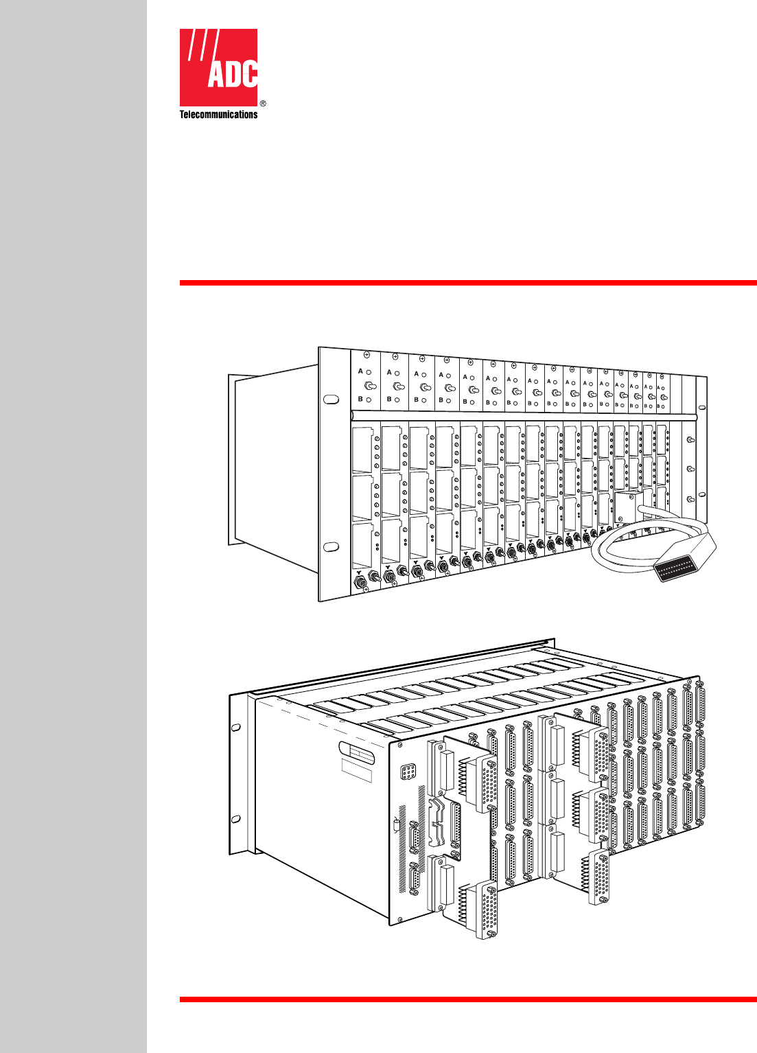
ADCP-50-304 • Issue 19 • June 1999 • Section 6: Installation POWER INTERFACE SUPPLY CONNECTORS CONNECTOR COMMUNICATIONS CHANNEL CONNECTORS DTE (A) CONNECTORS DTE (B) CONNECTORS DCE CONNECTORS 1559-A INTERCHASSIS INTERLOCK Figure 6-1. RDC-01/02 PatchSwitch Chassis Rear View 1.5 Communications Network Interface Connections The back of each PS chassis (see Figure 6-1) contains 50 standard D-sub 25 pin connectors used to interface PatchSwitch modules with a communications network.
ADCP-50-304 • Issue 19 • June 1999 • Section 6: Installation DCE/DTE BERG POST FOR DSR JUMPER DIP SOCKET BERG STRAP RSP CMD SEL CTL U3 U5 U4 U1 DTE U2 DCE U6 PROGRAMMING PLUG 1635-A Figure 6-2. Data Converter Module 1.6 Control Module DIP Switch Settings When PatchSwitch equipment is configured for serial remote control, the chassis address must be selected on each control module. For dc pulse control, the chassis address is ignored.
ADCP-50-304 • Issue 19 • June 1999 • Section 6: Installation Table 6-1 shows the binary switch settings corresponding to the identifying PS chassis addresses. Table 6-1.
ADCP-50-304 • Issue 19 • June 1999 • Section 6: Installation 2 CONTROL MODULE AUTOFALLBACK JUMPER INSTALLATION When the autofallback option is selected, the proper jumper must be installed on the CM (Figure 6-4) before the module is installed in the PS chassis. Each CM has a group of four jumper selections located on the side of the circuit board. Refer to Figure 6-5 for an illustration of the autofallback jumpers.
ADCP-50-304 • Issue 19 • June 1999 • Section 6: Installation AUTO SW B AUTO SW A INTLK V STORE 1568-A Figure 6-5. Autofallback Jumpers 3 CONTROL MODULE REMOTE CONTROL JUMPER INSTALLATION The CM is factory set to configure the 9-pin D-subminiature connector as an RS-422 serial port. When the dc pulse control bank switching option is selected, the 2 × 8 jumper block must be installed on the dc pulse control side of the 3 × 8 jumper selections.
ADCP-50-304 • Issue 19 • June 1999 • Section 6: Installation 4 4.1 PS MODULE JUMPER INSTALLATION Interlock Jumper Installation If an interlock option is desired for the system, the proper jumper must be connected in each A/ B Switching Module before it is installed into the chassis. Each A/B Switching Module has five interlock jumper positions. One jumper position for each of four interlock groups (labeled “1” through “4”) and one vertical interlock group (labeled “V” or “Store”).
ADCP-50-304 • Issue 19 • June 1999 • Section 6: Installation 4.3 Automatic Alarm Reset Jumper Installation The automatic reset jumper must be installed before the module is installed in the chassis. Each module with the alarming feature has automatic reset and store jumper contacts in the lower right corner of the component side as shown in Figure 6-7. The alarm automatically resets when the jumper is on the left set of contacts. The jumper may be stored (i.e.
OPERATION
ADCP-50-304 • Issue 19 • June 1999 • Section 7: Operation SECTION 7: OPERATION Content Page 1 GENERAL . . . . . . . . . . . . . . . . . . . . . . . . . . . . . . . . . . . . . . . . . . . . . . . . . . . . . . . . . . . . . . . . . . . . . . . . . . . .7-2 2 PATCHING — IN-LINE ACCESS MODULES . . . . . . . . . . . . . . . . . . . . . . . . . . . . . . . . . . . . . . . . . . . . . . . . . . . . . .7-2 2.1 Monitor Patching . . . . . . . . . . . . . . . . . . . . . . . . . . . . . . . . . . . . . . . .
ADCP-50-304 • Issue 19 • June 1999 • Section 7: Operation 1 GENERAL The PS equipment functions in either patching or switching methods of operation. The patching operations include intrusive monitor and interface while the switching operations are performed either locally or remotely. 2 PATCHING — IN-LINE ACCESS MODULES In patching operations, patch cord connections are made through the front of the PS equipment modules.
ADCP-50-304 • Issue 19 • June 1999 • Section 7: Operation The middle port functions in a similar manner for the middle connector on the chassis rear panel. When in the “B” state, monitor access; “A” state, test access to the off-line “B” device. The lower port provides intrusive access to the lower connector on the chassis backplane. Insertion of a patch cord in this port, regardless of switch status, breaks the circuit and connects the patchcord to the common (DCE) device.
ADCP-50-304 • Issue 19 • June 1999 • Section 7: Operation Table 7-1. Control Switches NAME AB MASTER Momentary Toggle A/B switch operates all 16 chassis modules with A/B switching function to the A or B DTE channel position. ENABLE Momentary Toggle In either up or down position, enables operator to make an A/B switch (both channel and gang). ALARM RESET Meomentary Toggle In either up or down position, enables operator to reset PS chassis modules alarm(s) from on to off.
ADCP-50-304 • Issue 19 • June 1999 • Section 7: Operation 6.3 Bank Switching Bank switching is performed by the operator toggling the A/B MASTER switch (located on the Control Module) to either the A or B position and then toggling the ENABLE (directly below the A/B MASTER switch) switch (off-center position). This operation causes all of the PS chassis modules to switch to the channel (A or B) corresponding to the selection of the A/B MASTER switch.
ADCP-50-304 • Issue 19 • June 1999 • Section 7: Operation 6.6 Remote Control Switching The PatchSwitch Control Module is capable of controlling the PS chassis modules by responding to commands received on the communications channel from a remote control device with the remote control jumper block in the RS-422 serial communications position.
ADCP-50-304 • Issue 19 • June 1999 • Section 7: Operation Non-digit and non-blank characters are recognized by the CM software as parameter separators. Therefore, two such consecutive characters (non-digit and nonblank) are recognized as a null parameter. Each null parameter is replaced with a default value assigned by the CM software. If the null parameter does not have a legal default value assigned to it, the CM issues an error message to the remote control device. 6.
ADCP-50-304 • Issue 19 • June 1999 • Section 7: Operation In the next example, the system would not interpret the GO command from the strings: bGO (b meaning blank) GGO As previously stated, commands may be entered in either upper or lower case alpha characters. Case has no effect on the CM interpretation. 6.
ADCP-50-304 • Issue 19 • June 1999 • Section 7: Operation 6.13 Select PS Chassis Command The remote control device selects a PS chassis by issuing an activation command containing the chassis' identification number. Chassis' identification numbers are determined by the settings on the DIP switch located on the chassis CM. Refer to Section 6 for a description of the DIP switch settings. There are four different select commands acceptable by the CM.
ADCP-50-304 • Issue 19 • June 1999 • Section 7: Operation 6.15 Request Software Revision Level (REV) Command) The REV command requests the CM to transmit the software revision level. The REV command string must contain a command flag (# or $) prior to the line feed (LF) character. If an echo flag occurs in the command string, the user must issue a GO command before the PS chassis will return the revision level message.
ADCP-50-304 • Issue 19 • June 1999 • Section 7: Operation 6.18.2 Module Position Entries Some displays are instructions to enter the numerical module positions of A/B Switch Modules. To enter module numbers enter each number, separated by commas (Example: 3, 7, 11, 14) and press RETURN. The comma is always used as an input delimiter. Two or more A/B Switch Module numbers in a sequence may be entered as a group by entering the lowest and highest numbers in the sequence, separated by a dash (Example: l-4).
ADCP-50-304 • Issue 19 • June 1999 • Section 7: Operation 6.19 TLKxx Execution CRT actions and displays involved in operating in the TLKxx format are shown in Figure 7-1 and defined in Table 7-3. Enter TLKxx with xx equal to the two-digit chassis address (00 to 15) and press RETURN. Completion of chassis selection always results in a status display of the selected chassis followed by the Select Operation Menu.
ADCP-50-304 • Issue 19 • June 1999 • Section 7: Operation Table 7-3. Chassis Selection and Configuration via TLKxx Command ACTION DISPLAY Enter: TLKxx Entry of TLKxx displays: GS application xxxxxxxxxxx on-line or GS application xxxxxxxxxxx failed followed by: Chassis No. XX xxxxxxxxxxx Application Module # 0 l 2 3 4 5 6 7 8 9 10 11 12 13 14 15 Sw Status Select Operation l. Switch 2. Setup 3.
ADCP-50-304 • Issue 19 • June 1999 • Section 7: Operation Table 7-4. Change Switch Selection ACTION/DISPLAY DISPLAY DEFINITION Enter 1. Switch from the Select Operation Menu to display the present switch status followed by: Select Switch Action l. Normal (A) 2. Substitute (B) 4. Configuration Switch Ctrl X To Exit (--) > l. Normal (A) – Selects Equipment channel A on A/B Switch Modules. 2. Substitute (B) – Selects Equipment channel B on A/B Switch Modules. 3.
ADCP-50-304 • Issue 19 • June 1999 • Section 7: Operation Table 7-4. Change Switch Selection, continued ACTION/DISPLAY Enter 7. Configuration Switch from the Select Switch Action Menu to display: Select Configuration l. (11 Characters) 2. (11 Characters) 3. (11 Characters) 4. (11 Characters) 5. (11 Characters) Ctrl X To Exit (--) > Enter the desired predefined configuration: This entry displays: Chassis No.
ADCP-50-304 • Issue 19 • June 1999 • Section 7: Operation Table 7-5. Change Switch Status ACTION/DISPLAY DISPLAY DEFINITION Enter 3. Status from the Select Operation Menu to display: Select Status Action l. Display Status 2. Save Current as Configuration Ctrl X To Exit (1) > To save the current configuration enter 2. Save Current as Configuration from the Select Status Action Menu. This entry displays: Select Configuration to Display or Replace l. xxxxxxxxxxx 2. xxxxxxxxxxx 3. xxxxxxxxxxx 4.
ADCP-50-304 • Issue 19 • June 1999 • Section 7: Operation SELECT OPERATION SWITCH 2. NO COMMAND ACTION INCOMPLETE RETRY COMMAND? COMMAND ACTION COMPLETE DISPLAY OF STATUS 1. YES 1. NORMAL (A) SELECT SWITCH ACTION SWITCH TO (A) NORMAL 2. SUBSTITUTE (B) CARD SELECTION DISPLAY OF NEW CHASSIS CONFIGURATION SWITCH TO (B) SUBSTITUTE 3. INVERT (AB) INVERT SWITCH STATUS OR CONFIGURATION SWITCH DISPLAY OF SELECTED CONFIGURATION SELECT CONFIGURATION SWITCH TO DISPLAYED CONFIGURATION 1.
ADCP-50-304 • Issue 19 • June 1999 • Section 7: Operation 6.20 SPKxx Format When a remote control device selects a PS chassis by issuing a “SPKxx” command, and then requests status by issuing a “UP#” command, the CM responds with the condensed status format. The condensed status format is a string of eight hexadecimal digits representing the switch positions and alarm conditions for all 16 module slots contained in the selected PS chassis. The “SPKxx” command is used by the RCU.
ADCP-50-304 • Issue 19 • June 1999 • Section 7: Operation Table 7-6. “SPKxx” Command Status Responses KEY IN RESPONSE DEFINITIONS OR COMMENTS SPK01 RDY01 Chassis 01 selected UP Request status update 56A31010 516 = 010102 = Modules l5 and l3 in “A” switch position. Modules l4 and l2 in “B” switch position. 616 = 01102 = Modules 11 and 8 in “A” switch position. Modules l0 and 9 in “B” switch position. A16 = 10102 = Modules 6 and 4 in “A” switch position. Modules 7 and 5 in “B” switch position.
ADCP-50-304 • Issue 19 • June 1999 • Section 7: Operation The format for the AL command string parameters is as follows: AL, , , , , CRLF The CM issues an error message if any parameter value is not within the specified range of values. An error message occurs if the startslot value is greater than the endslot value. Note: Alarm conditions are always reported to a Remote Control Unit (PSR-03) and terminal.
ADCP-50-304 • Issue 19 • June 1999 • Section 7: Operation flag ($) occurs in the AB command string, the user must issue a GO command to perform the switching operations. If an execute flag (#) occurs in the AB command string, the CM executes the AB command string immediately when it is received. Caution: When using Autofallback, the operator’s switching commands may be negated. That is, modules in alarm state switch to the side specified by the jumper (A or B).
ADCP-50-304 • Issue 19 • June 1999 • Section 7: Operation 6.24 Request Super Chassis Command (SC Command) The SC (Super Chassis) command is a quick-switch feature used by the remote control device (terminal) to simultaneously select multiple chassis. This command is normally used in conjunction with a subsequent AB or AL command to perform AB switching and/or to enable alarm reporting after the chassis are selected. All chassis selected by the SC command, have their status response “silenced”.
ADCP-50-304 • Issue 19 • June 1999 • Section 7: Operation Table 7-9. Request Super Chassis, SC Command String Parameters and Definitions, continued OPERATION COMMAND STRING PARAMETERS DEFINITIONS OR COMMENTS Enable/Disable Alarm Status Reporting AL,w,x,y,z# Refer to Enable/Disable Alarm Status Reporting definitions listed in Table 7-7. Where: AL - indicates alarm status operation.
ADCP-50-304 • Issue 19 • June 1999 • Section 7: Operation l7,2000 If no change in status occurred in the SwitchMate System, the CM cannot execute the UP command. 18,1000Parameter syntax error in AB command. 19,1001Invalid action parameter in AL command. 19,l002 Invalid cardtype parameter in AL command. 19,1003Invalid startslot number in AL command. 19,1004Invalid endslot number in AL command. 19,1005Startslot number is greater than endslot number in AL command. 6.
GENERAL INFORMATION
ADCP-50-304 • Issue 19 • June 1999 • Section 8: General Information SECTION 8: GENERAL INFORMATION Content Page 1 WARRANTY/SOFTWARE . . . . . . . . . . . . . . . . . . . . . . . . . . . . . . . . . . . . . . . . . . . . . . . . . . . . . . . . . . . . . . . . . .8-1 2 REPAIR/ADVANCE REPLACEMENT POLICY . . . . . . . . . . . . . . . . . . . . . . . . . . . . . . . . . . . . . . . . . . . . . . . . . . . . .8-1 3 REPAIR CHARGES . . . . . . . . . . . . . . . . . . . . . . . . . . . . . . . . . . . . . .
ADCP-50-304 • Issue 19 • June 1999 • Section 8: General Information 3 REPAIR CHARGES If the defect and the necessary repairs are covered by warranty, Buyer’s only obligation is the payment of all transportation and associated costs in returning the defective Product to the location designated by ADC. ADC, at its option, will either repair or replace the Product at no charge and return the Product to Buyer with transportation costs paid by ADC, only when ADC contracted carriers are used.
ADCP-50-304 • Issue 19 • June 1999 • Section 8: General Information 6 CUSTOMER INFORMATION AND ASSISTANCE For customers wanting information on ADC products or help in using them, ADC offers the services listed below. To obtain any of these services by telephone, first dial the central ADC telephone number, then dial the extension provided below. The central number for calls orginating in the U.S.A. or Canada is 1-800-366-3891. For calls originating outside the U.S.A.