GFA-7700 High Current 5-Channel Power Amplifier Owner’s Manual
GFA-7700 Features • Precision-matched devices used throughout the signal path. • 120,000 µF of power supply-filter capacitance for greater reserve capacity. • Independent power supplies for each channel. • Fewer gain stages improve signal reproduction accuracy. • Custom toroidal power transformer provides better regulation and greater peak current capability. • Independent thermal-overload and distortion LEDs for all 5 channels. • High quality, gold-plated 5-way binding posts.
Introduction Congratulations on your decision to purchase the GFA-7700, 5-channel power amplifier. The GFA-7700 integrates very well with any other home theater system, such as Dolby ProLogic™ or Dolby Digital™. You have made a wise choice that will reward you with exceptionally accurate and musical sound reproduction for years to come. To realize the full potential of your new amplifier, please read these operating and installation instructions thoroughly before attempting to make any connections to it.
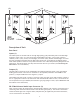
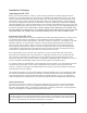
(3) (1) (2) (4a) (4b) Description of Unit Rear Panel Inputs (1) The audio inputs for the GFA-7700 are through high-quality, gold-plated RCA jacks to minimize highfrequency losses, noise, etc. They will accept standard RCA-type plugs, one for each of the five channels; Front L (Left), Center, Front R (Right), Surround L (Left), and Surround R (Right). To insure that the performance designed into the GFA-7700 is preserved, you should use the highest quality audio cables possible.
12VDC Triggering (4a) The GFA-7700 is a very high power amplifier and as such must be directly connected to the wall outlet or an appropriate surge protector or AC line conditioner. It must never be connected to the “switched” outlets on the rear panel of a pre-amplifier. Usually this would mean that when you turn on/off your pre-amplifier you would have to turn on/off your power amplifier separately.
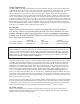
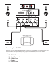
(6) (7) (9) (8) Front Panel On/Off Switch (6) The On/Off Switch controls power to the power transformer and circuits of the GFA-7700. Whenever the GFA-7700 is energized the Power LED (7) will glow. To turn the GFA-7700 on, press the push-button. It will remain in the “engaged” position while the unit is energized. To turn the GFA-7700 off, press the push-button in and release and it will move to the “disengaged” position.
Distortion Alert LEDs (8) The Distortion Alert circuit is a unique ADCOM distortion detection system which reads all forms of nonlinear distortion such as THD, IM, slew-induced, “clipping,” etc. The Distortion Alert LEDs will light when distortion reaches approximately 1% regardless of impedance, voltage/current phase angle or the reactance of the loudspeakers which the amplifier is driving.
Installation & Hookup Unpacking the GFA-7700 Before your new GFA-7700 left our factory, it was carefully inspected for physical imperfections and tested for all electrical parameters as a routine part of ADCOM’s systematic quality control. This, along with full operational and mechanical testing, should ensure a product flawless in both appearance and performance. After you have unpacked the GFA-7700, inspect it for physical damage.
Connecting the GFA-7700 Remember, that the Left and Right designations are as you are sitting down in your listening/viewing area. On the rear panel, the inputs and outputs are grouped in 5 bracketed sets, one for each channel.
Inputs (1) To preserve the correct effects, be certain to connect the RCA cables to the proper RCA-input connector. If the cables are color coded, then use this sequence for the connections: Blue............................................................ Left Front Red ........................................................... Right Front Green.............................................................. Center White with Blue Stripe .................................
It is suggested that the three front channels follow this chart for speaker lengths and wire gauges. up to 24 feet...................................... AWG16 up to 36 feet...................................... AWG14 up to 58 feet...................................... AWG12 Generally, for the two rear surround channels, longer runs of cable are needed, but since less program material is being transmitted through the cable, longer runs are acceptable: up to 48 feet......................................
Troubleshooting Resolving Problems Use the chart below to solve common situations that don’t require professional attention. If the steps stated in POSSIBLE SOLUTION do not resolve your problem, then please contact your ADCOM Dealer or call the ADCOM Customer Service Department. Any problems not covered here should be brought to the attention of your ADCOM Dealer or ADCOM Customer Service Department.
Servicing ADCOM has a Technical Service Department to answer questions pertinent to the installation and operation of your unit. In the event of difficulty, please contact us for prompt advice. Please have the following information readily at hand: the unit’s model and serial numbers, and dealer from whom it was purchased. If your problem cannot be resolved through our combined efforts, we may refer you to an authorized repair agency, or authorize return of the unit to our factory.
GFA-7700 Specifications THD + Noise into 8 ohms (Typical) 20Hz...............................................................................................................0.006% 1kHz...............................................................................................................0.006% 10kHz...............................................................................................................0.02% 20kHz...................................................................................
8551 East Anderson Drive, Suite 105 Scottsdale, Arizona 85255 Voice: (480) 607-2277 Fax: (480) 348-9876 www.adcom.