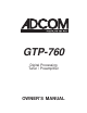
GTP-760 Digital Processing Tuner / Preamplifier OWNER’S MANUAL
This page should be picked up from any Adcom manual second page (inside front cover) 1
SAFETY NOTIFICATION PAGE This equipment generates and uses radio frequency energy and if not installed and used properly (that is, in strict accordance with the manufacturer’s instructions), may cause interference to radio and television reception. It has been type tested and found to comply with the specifications Subpart J of Part 15 of FCC rules, which are designed to provide reasonable protection against such interference in a residential installation.
A NOTE FROM ADCOM Thank you and congratulations on your purchase of the ADCOM GTP-760 Digital Processing Tuner/Preamplifier. The GTP-760 forms the centerpiece of a truly leading edge home theater system. To deliver the highest possible performance, ADCOM designers and engineers utilized the most advanced digital signal processing “engines” available, the Motorola 56000 series.
Table of Contents PRELIMINARY INFORMATION.....................................................................p. 2 Safety Information A Note from ADCOM The ADCOM Protection Plan Unpacking your GTP-760 1.0 PRODUCT FEATURES..........................................................................p. 6 1.
LD input VCR input and output Video aux input Room 2 output Video monitor outputs Video Processor input and output Video Processor On/Off switch Remote control connections Infrared repeater outputs Remote sensor extension outputs Preamplifier outputs 5.1 Channel inputs AC fuse holder AC power cord AC convenience outlet 1.3 The Remote Control..................................................................................p. 19 2.0 INSTALLING/CONNECTING THE GTP-760..........................................
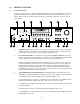
1.0 PRODUCT FEATURES 1.1 Front Panel Controls The GTP-760’s front panel is a model of simplicity. All controls are logically grouped for easy, intuitive operation. Familiarize yourself with the following diagram and read the short explanations of each feature. When you finish, you will be well on your way to enjoying the GTP-760’s convenience and sound quality. 3 D I G I T A L G T P - 7 6 0 phones 3 DTS Dolby Digital Cinema Dolby Pro Logic symphony hall stadium jazz club 5-chan. stereo 2-chan.
For familiar music CDs (also called PCM signals) the choices are the same as for analog inputs, Dolby Pro Logic, Dolby Pro Logic/Cinema, symphony hall, stadium, jazz club, 5-chan. stereo, and 2-chan. stereo. Because CDs do not carry Dolby Digital signals, the Dolby Digital option is not available and the GTP-760 automatically bypasses that choice.
1.2 13 5.1 Channel In Button: This button selects the 5.1 channel analog input, which allows the user to enjoy high-resolution, multichannel formats such as DVD-Audio and Super Audio CD. This pure analog input completely bypasses any digital conversion or processing to maintain the highest possible audio quality; thus, delay and bass management are disabled and no surround modes may be selected when using the 5.1 channel analog input. This input is selectable from the front panel only.
Composite or S-Video? One of the first system hook-up decisions to make will be which video format to use. While the composite video format is more widely used, S-Video can offer improved picture quality. The GTP-760 does not convert between the two formats. However, it can save the video mode for each input. It is recommended that only one video format be used as this simplifies normal operation. However, setup for using both formats is also described below.
18 19 20 21 22 23 18 Antenna connections Digital audio/standard (composite) video inputs DVD Digital 2 Digital 1 ( RF ) Digital 1 RF Demodulator switch 12 volt trigger output Analog audio/standard (composite) video inputs and outputs LD (laserdisc) inputs VCR inputs and outputs Video aux in Room 2 outputs Video Processor inputs and outputs Tape inputs and outputs Standard (composite) video monitor outputs CD inputs S-Video inputs and outputs DVD input Digital 2 input 24 25 26 27 28 29 Digital 1 input
For FM, use either the 75 ohm “F” connector or the 300 ohm “push terminals” depending on what type of antenna you’ve chosen. If you’re getting FM from a cable system feed, you will most likely use the “F” connector. The “T” shaped antenna supplied with the GTP-760 uses the push terminals marked “300 ohms.” “T” antennas are directional. They should be placed as high as possible with the arms fully extended. If possible, the arms should be oriented so that they are at right angles to the transmitter.
DVD in digital 2 in LD in digital 1 in 12V trigger out DVD in digital 2 in digital 1 in Standard video in L dig 1 RF demodulator R in out Video) to the appropriate “dig.2 in” jack. Digital 2 in: This input is recommended for an audio/video source (DSS receiver, etc.) with a TOSlink (optical) digital output. Remember that the composite video connection will go to the yellow-center RCA jack immediately under the “dig.2 in” label.
21 12 Volt Trigger Output (see illustration on preceding page) To facilitate remote turn-on and turn-off of other components (power amplifiers, for example), this 2.5 mm mini-jack provides a constant signal (12 volts DC) whenever the GTP-760 is fully powered. When the GTP-760 is turned off (via the front panel switch) or placed in standby mode (via the “power” button on the remote control), the jack has no output.
Video Aux Input: This input is electrically identical to the LD input described above and will accommodate a wide variety of audio/video sources. After selecting and connecting the source’s composite or S-Video output to the GTP-760’s corresponding “video aux” video input, connect the source’s left channel analog audio output to the white RCA jack under the “video aux in” label. Then connect the source’s right channel analog audio output to the red RCA jack under the “video aux in” label.
Tape Inputs and Outputs: These connections are designed for a cassette deck or any other audio recording device with line-level analog inputs and outputs. tape in out CD L R Follow these instructions: 1) Connect the recorder’s left channel analog audio output to the GTP-760’s white “tape in” jack. 2) Connect the recorder’s right channel analog audio output to the red “tape in” jack. 3) Connect the recorder’s left channel analog audio input to the GTP-760’s white “tape out” jack.
23 S-Video Inputs and Outputs Note: This section assumes that you’ve elected to use S-Video sources and display devices and that you’ve set the GTP-760 for S-Video signal transfer by following the steps described in the boxed note entitled Composite or S-Video? on page 9.
24 Video Processor On/Off Switch This switch controls a “video loop” that enables the GTP-760 to function with a separate video processor. 25 For conventional home theater systems, make sure the “video processor on/off” switch is in the OFF position. When using a separate video processor, place this switch in the ON position. Remote Control Connections remote sensor extension IR repeater .
27 5.1 Channel Inputs front rear subwoofer center These are the multichannel analog inputs. Connect your DVDAudio, SACD or other multichannel source as follows: 5.1-channel in 1) 2) 3) 4) 5) 6) Connect the source’s “front left” output to the white-centered RCA input marked “front”. Connect the source’s “front right” output to the red-centered RCA input marked “front”. Connect the source’s “surround left” output to the white-centered RCA input marked “rear”.
29 AC Convenience Outlets (115VAC models) These outlets are for low-current source components only. They are not designed for power amplifiers. The single unswitched outlet is live whenever the GTP-760 is plugged into a live AC source. The two switched outlets are live only when the GTP-760 is fully operational (i.e., whenever the front power button’s LED is red.) They are not live when the GTP-760 is in standby mode (when the LED is yellow.
30 31 32 33 34 35 36 37 38 39 40 41 42 43 44 45 46 47 48 49 50 51 52 53 54 55 56 57 Source selectors main DVD dig.1 (digital RF — digital LD) dig.2 (digital auxiliary) tuner CD VCR v. aux (video auxiliary) Power Input selectors Volume Up/Down Tuning Up/Down Guide Menu < (left arrow) Up arrow/Pause > (right arrow) Down arrow/Stop Select/Play Direct access keypad (“1” through “10” and “+10”) Shift FM/AM Stereo Srnd (surround) Enter d.
30 Source Selectors (main, DVD, VCR, tuner, v. aux, CD, dig.1, dig.2.) These buttons serve two functions. • First, they switch inputs on the GTP-760 so you can hear the source you’ve just selected. • Second (and even more important), they can change the functions of all the other buttons on the remote controller. In other words, if you first push the DVD device selector, the remote’s select/play button generates a command code for your DVD player. If you then press the dig.
40 Down arrow/Stop • In main mode, this is preprogrammed to scroll down to the next choice on a menu screen. • In CD mode, it is preprogrammed to stop an ADCOM CD player. • In tuner mode, it is preprogrammed to start scanning preset frequencies lower than the current station. • The button is programmable for use with any other source. 41 Select/Play • In main mode, this is preprogrammed to enter a selection chosen via the menu system. • In CD mode, it is preprogrammed to start an ADCOM CD player.
50 Level trim (Rear Up/Down, Center Up/Down, Sub Up/Down) Rear Up • In main mode, button is preprogrammed to increase both rear speaker levels simultaneously. • In CD mode, button is preprogrammed to access disc 2 with ADCOM disc player. • The button is programmable for use with any other source. Rear Down • In main mode, button is preprogrammed to decrease both rear speaker levels simultaneously. • In CD mode, button is preprogrammed to clear “repeat” command with ADCOM disc player.
Remote Function Table This table supplements the information you’ve just read. Use it to quickly review button functions. The controller’s capabilities are extensive and may be somewhat intimidating at first. However, you will soon find that its logical button arrangement and programming capabilities will greatly increase your enjoyment as you discover the ease with which you can operate your entire system from just one remote! Look down the left-hand column until you see the button you want to learn about.
BUTTON FUNCTION Main CD Tuner All Others 0 + 10 SHIFT FM/AM STEREO SRND ENTER D. RANGE REAR + CENTER + SUB + BAL. CHK Not programmable Track 10 + 10 Call Repeat Program/Mem.
For tuner functions (changing stations, etc.): 1. 2. Press the tuner source selector button. It will flash red. Press the tuning up (or tuning down) function button to change stations. The tuner source selector will flash red to confirm that the function button you’ve selected actually triggers a command. (Again, use the table to see which buttons are preprogrammed.) Press the CD source selector first to access preprogrammed commands for ADCOM CD players.
Deleting (clearing) Individual Programmed Commands 1. Press the ADCOM remote’s source selector and select/play buttons simultaneously and hold until the orange status LED and the source selector button glow steadily. 2. Press the function button you wish to clear. The status LED will flash continuously. 3. Press the backlight button. The status LED will then flash green twice and then revert to steady orange. The source selector button will continue to glow.
m1 button is pressed IF main, DVD, dig. 1, or dig. 2 sources are active at the time you select that macro. If you’ve programmed a Group 2 macro, it will send out an identical command sequence whenever tuner, CD, VCR, or v. aux inputs are active. Programming Macro Initiator Buttons: 1. Press either the Group 1 or Group 2 source selector button (main or tuner respectively) and the mute button simultaneously. Hold both buttons until the red status LED and the input selector button remain lighted. 2.
3.0 INITIAL SETUP What this section is all about . . . After connecting your home theater, you may elect to configure the GTP-760 to the specific speaker arrangement and dimensions of your system. The procedures described in this section demonstrate how to use the GTP-760’s on screen display to enter this information. Once complete, the GTP-760 stores this information so that these tasks need only be repeated if speakers are changed or substantially repositioned.
In a typical home theater system, the distance from each speaker to the listening position will be different. The most common example: in many home theaters the center and rear speakers sit closer to the listener than the main speakers. In such a situation the sound emitted from the closer speakers will be heard first. For many movie soundtracks the effect of this may be very mild, perhaps unnotice able. In others, it can be subtly distracting.
The speaker size menu allows you to describe the size and number of speakers in your system to the GTP-760. The descriptive words LARGE and SMALL that appear in the MAIN field mean the following: LARGE: The speaker is full range and capable of reproducing the entire audible frequency spectrum 20Hz to 20kHz. The GTP-760 sends a full range signal to LARGE speakers without any crossover filtering.
3.4 CHANNEL BALANCE > > From the SETUP screen, select CHANNEL BALANCE with the or buttons and press select/play. You will see: CHANNEL BALANCE LEFT RIGHT CENTER REAR L REAR R SUB - + + + + + + UNDO CHANGES DONE Each piece of home theater equipment operates differently. In the same system, amplifiers may have different gains, speakers may have different efficiencies and, as already discussed, speakers may be positioned in different manners relative to the listener.
Second, the subwoofer trim appears in the CHANNEL BALANCE menu, but not during the operation of the noise sequencer. Because the subwoofer operates at a limited frequency range and because the sound level measurement is weighted, the noise sequencer method of channel trimming is often unreliable in setting the subwoofer level. Using such an approach can sometimes lead to “pegging” the subwoofer trim to its highest level on the GTP-760 to compensate.
> > If you have chosen to use a mix of both Composite and S-Video sources, the VIDEO field of the INPUT SETTINGS menu is the place to set the mode. In the example from section 1.2, a composite VCR and an SVideo DVD are to be used. Select the VCR input of the GTP-760. The VIDEO field should show COMPOSITE. Now select the GTP-760 input where the DVD player is connected (DVD, digital 1 or digital 2). Highlight the VIDEO field and press either the < or > remote button.
When you are using analog inputs, you will probably need to manually select the proper operating mode. However, the GTP-760 remembers the mode you’ve most recently used for a particular input and will automatically restore that mode when you use that input next, software permitting, of course. You can change modes with the menu system or with the surround mode button when you wish.
4.2 The Tuner Selecting stations 1) Select the tuner input via the front panel or remote control button. The information display will show the most recently received broadcast frequency. 2) If the band you want (AM or FM) is already displayed, proceed to step 3) below. If not, push the FM/AM selector to change to the appropriate band. 3) Choose your preferred tuning method (seek or manual) by pressing the front panel seek/manual button.
Listening to “Preset” Stations 1) Select tuner and either FM or AM. 2) Press the appropriate preset button (or shift + the preset button for choices higher than “preset 7”). 4.3 Room 2 Operation Introduction The GTP-760’s “Room 2” circuitry gives you the ability to simultaneously enjoy two different audio/video sources in two different areas of your home. For instance, you can watch a DVD movie in the main family room while someone else enjoys a satellite broadcast or CD in the bedroom.
Operating Room 2 From “Room 2” In addition to the front panel Room 2 controls, the GTP-760 provides an interface for controlling Room 2 remotely. Such a connection is technically sophisticated and usually intended only for custom installations. Please contact your ADCOM dealer or ADCOM directly for further information on these advanced features and capabilities. 5.0 TROUBLE SHOOTING Your GTP-760’s circuitry is built around advanced microprocessors.
Note 1: Cable TV systems can contribute to ground loop problems, which in turn, cause “hum.” To determine whether your cable system is the contributing factor, disconnect the cable TV incoming signal line (the round, 75 ohm cable) before it first connects to your system. If the hum disappears, you should insert a “75 ohm Ground Loop Isolator” between the cable down lead and your system. Check with your ADCOM Dealer to obtain one.
6.0 CARE, MAINTENANCE, and SERVICE CARING FOR YOUR GTP-760 ADCOM has taken great care to ensure your GTP-760 is as flawless in appearance as it is electronically. The front panel is a heavy gauge, high-grade aluminum extrusion carefully finished and anodized for durability. The chassis, top cover, and rear panels are powder-coated heavy gauge steel that have been baked to ensure a lasting, durable finish.
7.0 SPECIFICATIONS GTP-760 Preamplifier Section Output Level (Rated)................................................................................................1.0V Input Impedance.............................................................................................20k Ohms Output Impedance...........................................................................................560 Ohms Frequency Response 20Hz to 20kHz..........................................................................
This page has been interntionally left blank.
10 Timber Lane Marlboro, NJ 07746 Tel: (732) 683-2356 Fax: (732) 683-9790 www.adcom.com (c) 2000 by ADCOM. All rights reserved. Printed in the USA GTP-760/v.1.