
Owner Manual Digital Processing Tuner/Preamplifier GTP-860II

| ADCOM GTP-860 II Owner’s Manual10
11ADCOM GTP-860 II Owner’s Manual |
FM Antenna: A ribbon wire FM anten-
na is included and should be connect-
ed to the FM connector at the rear
of the unit using the ‘balun’ adapter
supplied. The ribbon aerial should be
mounted on a vertical surface and
placed so that it forms a ‘T’.
Experiment with placement of the
antenna to find the position that
gives the best signal strength and
lowest background noise. An inad-
equate FM signal normally results in
high levels of hiss, especially in ste-
reo, and interference from external
electrical sources. In areas of poor
FM reception, the tuner section’s per-
formance can be improved by using
an externally mounted FM antenna. A
qualified aerial installer will be able
to advise and fit a recommended aer-
ial for your reception conditions.
[
11
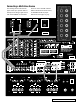
] Preamp Outputs
Before making any connections, check
that the GTP-860II and the power
amplifiers it will be connected to are
switched off. Connect the RCA-to-
RCA leads from the Front Left and
Right, Center, Surround Rear Left and
Right, and Surround Back Left and
Right Preamp Outputs to your external
amplifiers. The subwoofer preamp
output allows for connection to a
sub-bass speaker system with its own
external or integrated power amplifier
(“active” or “powered” subwoofers).
With volume turned down to a low
level, switch power on only after all
connections have been made.
[
12
] Auxiliary Outputs
The auxiliary outputs allow a line level
connection to various devices, such as
an audio system in another room. The
output is the selected source.
[
13
] Monitor Outputs
Composite Video and S-Video out-
puts are for connecting a TV or Video
Monitor to view video sources connect-
ed to Video 1 through Video 5. Using
a Video RCA-to-RCA lead or S-Video,
connect the ‘Video Line In’ on the TV
or monitor to the MONITOR OUT.
Note that an S-video input signal
will also be available as a composite
video signal on the Monitor out if
the corresponding source is selected.
Composite video input signals will
also be available as S-Video signals on
the Monitor output.
The video signal available on the S-
Video and Video Composite outputs
is dependent on the selected video
input (Video 1, Video 2, Video 3,
Video 4, Video 5). However, when one
of the audio-only sources is selected
(FM, AM, CD, Tape Monitor or ext
5.1) the last selected video signal
from one of the video inputs will be
present on these outputs. This way
you can watch a DVD player or video
while using the 5.1 analog audio
inputs from a DVD player, as you
might do when listening to a DVD-A or
SACD disc.
[
14
] Video/Analog Audio
Inputs & Outputs
Apart from the audio signal, these
inputs will also accept a video signal
which will be routed to the Monitor
Out sockets [13] for a television or
video projector. Composite connec-
tion (using the yellow RCA socket) or
an S-Video connection (using the Mini-
Din connector) is available.
The S-Video standard allows for high-
er quality video signal transfer when
compared to the Video Composite
standard. If your video components
have an S-Video connector use dedi-
cated S-Video leads to connect them
to the GTP-860II in the same way as
described with the Video Composite
equivalents.
A video signal fed to an S-Video input
socket will be available on both
the S-Video Monitor Out and Video
Composite Monitor Out.
Video 1 & Video 2: Inputs for the
audio playback and video signal from
a video device such as a stereo TV,
DVD player, satellite cable TV receiver
or a Laser Disc. Using twin RCA-to-RCA
leads, connect to the left and right
‘Audio Out’ of the video device to
these inputs. Using a single RCA-to-
RCA lead (Video Composite) or S-Video
lead, also connect the video output
of the video device. Video 1 & Video
2 can be used for video playback only.
Use Video 3 or Video 4 if you want to
connect a VCR for recording and play-
back through the GTP-860II.
Video 3 & Video 4: Connections for
the audio recording and playback to a
VCR or other video recorder. Using twin
RCA-to-RCA leads, connect to the left
and right ‘Audio Out’ of the VCR to the
Video 3 or Video 4 IN connectors for
playback. Connect the left and right
‘Audio In’ of the VCR to the Video 3
or Video 4 OUT connectors for record-
ing. Using a single RCA-to-RCA (Video
Composite) lead or S-Video lead, also
connect the video output of the VCR to
Video In for Video playback. Connect
the Video Input of the VCR to Video
Out of the GTP-860II preamplifier for
recording of video signals.
[
15
] Component Video
Inputs & Output
The GTP-860II can switch between
two sources with component video
output. The “video 1” and “video
2” sources have the capabilities to
accept component video signals. Each
component video signal uses three
RCA type connections (Y-green plug,
P
B
– blue plug, and P
R
– red plug), all
three connections should be made
for optimum video performance.
Be sure to use high quality video
specific cables for connection. The
Component video connection is inde-
pendent from the S-Video/Composite
video jacks. In order to maximize
signal quality, no On-screen text will
appear on the component outputs.
The “video component output” jacks
should be connected to component
video input on your TV.