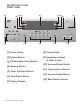
OWNER’S MANUAL GTP-860 G T P - 8 6 0 displ ay FM mute /high blend up volum e tune/ prese t mem ory down PROLOGIC II phones video L audio R CD tape monitor ext 5.
WELCOME Dear fellow ADCOM product owner, Welcome to the ADCOM family! For more than twenty years, ADCOM products have delivered excellent performance and value for customers around the world. Our products are designed by our experienced and demanding engineering team, built to the highest standards in our factory, and sold and serviced through dealers, custom installers, and other retailers whose primary goal is your complete satisfaction.
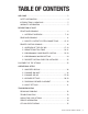
TABLE OF CONTENTS WELCOME .................................................. 2 SAFETY INFORMATION ..................................... 4 INTRODUCTION & UNPACKING ............................. 5 WARRANTY INFORMATION ................................. 5 DESCRIPTION OF UNIT FRONT PANEL DRAWING ................................... 6 1.1 INTERFACE OVERVIEW ........................... 7-10 REAR PANEL DRAWING ................................... 11 1.2 INPUTS & OUTPUTS SYSTEM CONNECTIONS ......
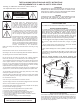
N OCK THE FOLLOWING PRECAUTIONS AND SAFETY INSTRUCTIONS ARE REQUIREMENTS OF UL AND CSA SAFETY REGULATIONS Warning: To reduce the risk of fire or electric shock, do not expose this unit to rain or moisture.
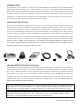
INTRODUCTION Congratulations on your decision to purchase the ADCOM GTP-860 tuner-preamplifier. The GTP-860 provides Dolby Digital and DTS decoding with 7.1 output channels, as well as a 5.1 analog bypass and the RDS radio data system. These features and ADCOM’s legendary quality provide the heart of your cutting-edge home theater. You have made a wise choice that will reward you for years to come with exceptionally accurate and musical sound reproduction.
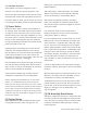
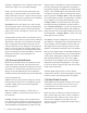
DESCRIPTION OF UNIT FRONT PANEL [1] [2] [4] [3] [9] [5] [6] [5 ] [7] [10] [11] [12] [1] Power Button [8] Volume Knob [2] Display Button [9] Headphone Output & Video 5 Input [3] FM Mute/High Blend Button [4] Memory Button [5] Tuner Up/Down Buttons [6] Tune/Preset Button [7] Display Window 6 | ADCOM GTP-860 OWNER’S MANUAL [8] [13] [10] Surround Backs Button [11] Input Selector Buttons [12] Surround Mode Button [13] Bass/Treble Controls
1.1 Interface Overview The GTP-860’s front panel is designed for ease of operation. All controls are logically grouped for easy, intuitive operation. Familiarize yourself with the preceding diagram and read the short explanations of each feature below. When you finish, you will be well on your way to enjoying the GTP-860’s convenience and sound quality. [1] Power Button Depress the Power button to switch the preamplifier to its ‘Stand-By’ mode. The amber LED in the power button will light up.
However, very weak radio station signals may be suppressed by the muting circuit. If such a very weak station is in stereo it will have a high level of background hiss. Switching to Mono Mode and disengaging the muting circuit by depressing the FM Mute/High Blend button will allow the station to be heard and will cancel most or all of this background noise. In normal operation the mute circuit is engaged, and the display indicates “FM MUTE.
search mode. When tuned accurately to a station, “TUNED” will light up in the display. [6] Tune/Preset Button The Tune/Preset button toggles between the Preset and Tune mode. When Preset mode is selected, “PRESET” lights up in the display area. Refer to the Tuner Up/Down button [5] description for more information. [7] Display Window The display area shows all vital information when the unit is operational.
switching is independent of the composite/S video signal and does not support on-screen display messages. ext 5.1: Selects the multi-channel output signal from a DVD player or external decoder source (such as DVDAudio) connected to the ext 5.1 input as the active input. NOTE: No ext 5.1 audio signal is available from the headphones socket, or the Tape, Video 3 or Video 4 outputs.
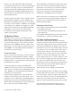
DESCRIPTION OF UNIT: REAR PANEL [20] [14] [15] [21] [22] [23] [16] [19] [17] [18] [28][26] [25] [27] [24] [14] Antenna Connections [21] Tape Inputs and Outputs [15] Preamp Outputs [22] CD Analog Inputs [16] Auxiliary Outputs [23] External 5.
1.2 Inputs & Outputs System Connectiotns Like the front panel, the GTP-860’s rear panel is carefully arranged to make hookup, configuration, and use as simple as possible. However, the GTP-860’s capabilities take some study to use most effectively. We strongly suggest that you read this section of the manual before beginning to hook up your system.
The video signal available on the S-Video and Video Composite outputs is dependent on the selected video input (Video 1, Video 2, Video 3, Video 4, Video 5). However, when one of the audio-only sources is selected (FM, AM, CD, Tape Monitor or ext 5.1) the last selected video signal from one of the video inputs will be present on these outputs. This way you can watch a DVD player or video while using the 5.1 analog audio inputs from a DVD player, as you might do when listening to a DVD-A or SACD disc.
right left digital input 75 ohm audio outputs serial number please visit www.adcom.com preamp outputs R L antenna AM FM cd video Y s-video R audio video 1 component input PR PB video 2 component input Y PB PR center digital audio in out IR input video 4 12v DC trigger in sub video 2 video 1 video 1 R R L L center in surr in video 4 video 2 in sub in R L L R ext 5.
[23] External 5.1 Analog Inputs International Setup Procedure Inputs for the multi-channel audio signals from an external decoder, such as an SACD or DVD-Audio player with integrated decoder. Use two twin RCA-to-RCA leads to connect the decoder’s front left and right ‘Audio Outputs’ to the Front left and right inputs, and the decoder’s Surround left and right outputs to the Surround left and right inputs.
[29] Source selectors [30] Power button [31] Input selectors [32] Mute button [56] [29] [30] [31] [38] [33] d. range [dynamic range] button main vid 1 vid 2 vid 3 vid 4 vid 5 tuner CD power tape [32] mute ext5.1 d.
REMOTE CONTROL 2.1 Overview of the GRC-800 The GRC-800 remote control is a learning remote control that is capable of saving commands for all remote controls in your home theater system. In this way, you may eliminate the confusion of using multiple remotes. Although such power comes with some added complexity, the complexity is minimal and with some repetition will become second nature.
[32] Mute Button [36] Play Button In all modes, this button is preprogrammed to mute outputs of device. Mute does not affect recordings made using the Tape outputs but will affect the signal going to the Preamp Outputs. When the unit is in mute mode, any adjustment of the Volume Control on the front panel [8] will release the muting, i.e. the original volume level will be resumed. In CD mode, it is preprogrammed for play with an ADCOM CD player.
[42] Test Button [49] RDS Button Pressing the test button engages the test signal generator to allow for adjustment of all speaker levels, so that each channel can be adjusted for equal loudness at your listening position. The test signal cycles automatically with 3second intervals from Front Left, Center, Front Right, Rear Right, Back Right, Back Left, Rear Left, to Subwoofer in continuous cycles.
2.2 Remote Function Table This table supplements the information you’ve just read. Use it to quickly review button functions. The controller’s capabilities are extensive and may be somewhat intimidating at first.
BUTTONS Main CD Tuner All Others RIGHT OSD Right Select Skip Ahead Programmable Programmable DOWN OSD Scroll Down Programmable Programmable Programmable LEFT OSD Left Select Skip Back Programmable Programmable SELECT OSD “Enter” Select Programmable Programmable Programmable 1 Not programmable Track 1 Programmable Programmable 2 Not programmable Track 2 Programmable Programmable 3 Not programmable Track 3 Programmable Programmable 4 Not programmable Track 4 Programm
2.3 Programming Your ADCOM GRC-800 Remote Controller The ADCOM universal remote controller operates eight different audio/video components. As you’ve already seen, it’s preprogrammed to control ADCOM’s GTP-860 Preamp/ Tuner and the GCD-700/750 CD players. In addition, it has seven “component memory banks” available so you can program the remote to learn commands for your DVD player, satellite box, laser disc player, VCR, etc. This lets you use one remote controller for your entire system.
Repeat Steps 3 through 5 for any other commands you want to teach your ADCOM remote for that source component. Deleting All The Programmed Commands for Every Source Component Save the commands you’ve just programmed into the ADCOM remote by pressing and holding the appropriate source selector and select buttons simultaneously. Hold until the status LED and source selector LED flash twice and then go out. Repeat these steps for any other source commands you wish to program.
For example, if the m1 button is programmed in Group 1 mode to turn on the TV, turn on the audio receiver, turn on the VCR, and then turn on the satellite receiver, it will perform the same series of commands whenever the m1 button is pressed IF main, vid 1, vid 2, or vid 3 sources are selected at the time you select that macro. If you’ve programmed a Group 2 macro, it will send out an identical command sequence whenever vid 4, vid 5, tuner, or CD inputs are selected.
FUNCTION and DATA list for GTP-860(ADCOM) Discrete (Direct Access) Custom Code: 1Ah E8h B: LSB first D: decimal Code Type: NEC2 Function Data(B) D Function Data(B) D * MAIN POWER ON * MAIN POWER OFF * DOLBY PRO LOGIC * SYMPHONY HALL * 2 CHANNEL STEREO * 5 CHANNEL STEREO * DOLBY PL II MOVIE * DOLBY PL II MUSIC * DOLBY PL II PANORAMA * DOLBY PL II MATRIX * Delay Front 5mS * Delay Front 4mS * Delay Front 3mS * Delay Front 2mS * Delay Front 1mS * Delay Front None * Dynamic Range Normal * Dynamic Range 7
OPERATION & SETUP After connecting your home theater, you may elect to configure the GTP-860 to the specific speaker arrangement and dimensions of your system. The procedures described in this section demonstrate how to use the GTP860’s on screen display to enter this information. Once complete, the GTP-860 stores this information so that these tasks need only be repeated if speakers are changed or substantially repositioned. 3.
results, start with the Left channel set at 0dB and to match the other channels to it. Normally, if the Right speaker is located at the same distance from the listening position to the Left speaker it should be set at the same level as the Left speaker. Highlight SAVE & EXIT and press Select to save the settings and return to the SETUP menu. Press the Test button again to leave or cancel the Test mode; any changes will be memorized automatically. 3.
Scroll through the preset delay time options and select the desired time. When both delays have been entered, choose “SAVE & EXIT” to save the settings and return to the Main Menu. In Dolby Digital surround mode, the rear channel delay time can be set from 0ms to 15ms with 1ms increments. The center channel can also be delayed up to 5ms, in 1ms steps. In Dolby Pro Logic surround mode, the rear channel delay time can be set from 15ms to 30ms and 1ms per step.
ately limited in dynamic range and frequency bandwidth for the surround channel and thus only requires speakers of far lesser capabilities compared to the front channels. Dolby Digital, however, is a full range system with two independent surround channels and with dynamics equal to that of the front channels. For this reason it is advisable to choose loudspeakers which are similar in power handling and performance capability to those of the front channels.
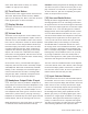
3.5 Surround Speaker Placement surround rear left front left center front right This speaker setting is preferred if you are not using surround backs. surround rear right surround rear left front left surround back left center This is the preferred speaker setting if you are using surround backs.
surround rear left 2-3 ft. Note: If space permits, install surrounds 2-3 feet above viewers.This helps to minimize localization effects. 3.6 Input Settings Input Settings shows information about the current state of operation of the GTP-860, and repeats much of the same information shown on the GTP-860’s front panel.
RESOLVING PROBLEMS Use the chart on the opposite page to solve common situations that don’t require professional attention. If the steps stated in POSSIBLE SOLUTION do not resolve your problem, then please contact your ADCOM Dealer or call the ADCOM Customer Service Department. Any problems not covered here should be brought to the attention of your ADCOM Dealer or ADCOM Customer Service Department.
SYMPTOM POSSIBLE REASON POSSIBLE SOLUTION No sound • Power AC lead unplugged or power not switched on • Tape Monitor selected • Mute on • Power Amplifier not on • Check if AC lead is plugged in and power switched on • De-select Tape Monitor mode • Switch off Mute • Turn on the Power Amplifier No sound on one channel • Speaker not properly connected or damaged.
CARING FOR YOUR GTP-860 Great care has been taken by ADCOM to ensure that your amplifier is as flawless in appearance as it is electronically. The front panel is a heavy-gauge, high-grade aluminum extrusion carefully finished and anodized for durability. The chassis, top cover and rear panel are heavy-gauge steel that has been powder coated and baked to ensure a lasting finish.
GTP-860 SPECIFICATIONS Input Impedance Audio . . . . . . . . . . . . . . . . . . . . . . . . . . . . . . . . . . . . . . . . . . . . . . . . . . . . . . . . . . . . . . . . . . . . . . . . . . . . . . . . 50k Ω Video . . . . . . . . . . . . . . . . . . . . . . . . . . . . . . . . . . . . . . . . . . . . . . . . . . . . . . . . . . . . . . . . . . . . . . . . . . . . . . . . . 75 Ω Output Impedance Audio . . . . . . . . . . . . . . . . . . . . . . . . . . . . . . . . . . . . . . . . . . . . . . . . . . . . .
ADCOM A division of Klein Technology Group, LLC 8551 East Anderson Drive, Suite 105 Scottsdale, Arizona 85255 Voice: (480) 607-2277 Fax: (480) 348-9876 http://www.adcom.