
User's Manual


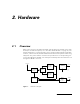
Table Of Contents
- 1. Introduction
- 2. Hardware
- 3. The A431 Radio Module
- 3.1. About the A431 Radio Module
- 3.2. Functional description
- 3.3. Manufacturing Issues
- 3.3.1. Marking and labeling issues
- 3.3.2. Alignment Range and Switching Range
- 3.3.3. Tuning Procedure
- 3.3.4. Setting Up the Default Parameters
- 3.3.5. Definitions
- 3.3.6. Test Equipment Settings
- 3.3.7. Trimming Elements
- 3.3.8. Adjusting the Receiver Front End
- 3.3.9. Adjusting the VCOs
- 3.3.10. Adjusting the Crystal Reference
- 3.3.11. Checking the Receiver Parameters
- 3.3.12. Checking the Transmitter Parameters
- 3.3.13. Data Transfer Check
- 3.6. Frequency Reference Specifications
- 3.7. A431 Module’s Photographs
- 4. Software

10
Hardware
For further details, consult the schematic diagram in Figure 2.
2.1.1. The Modem Interfaces
The low speed modem operates with two tones: 1 kHz (representing the “1” bits)
and 2 kHz (representing the “0” bits). A bit cell is represented by a complete time
period (
1/f
), thus the raw throughput varies between 1 and 2 kbps (average 1.5
kbps). The modem functions are essentially implemented in software by a separate
microprocessor. However, a signal pre-conditioning is performed on both receive
and transmit paths by means of two low-pass filters (U6 on receive and U19 on trans-
mit).
On receive, the buffered analog data signal from the radio unit is applied to a 3 kHz
low pass filter (U6). The filter output is further fed to the A/D input of a slave micro-
controller U5) performing the decoding operation for the low speed modulation
(see also “Modulation Technique Used (low speed modem)” on page 59). The slave
microcontroller (U5) communicates with the main microcontroller (U9) via a 4-wire in-
terface. In addition, the audio output from the radio unit is also applied to the GMSK
modem (U7) for decoding high speed data.
On transmit, the low speed data is generated again by the slave microcontroller (U5)
added by the R/2R network implementing a D/A converter. The slave microcontrol-
ler generates in effect the sinus waveforms required to encode the binary data. The
output signal is applied to the audio mixer U11, which adds the signal generated by
the high speed modem (U7). Obviously, only one modem will be activated at a time
by the master microcontroller (U9). The output signal of the mixer is applied to the
variable gain amplifier (U15) and then to the final low pass-filter (U19) that has a cut-
off frequency of around 7 kHz.
The high speed modem (U7) has two clocking options: either it can be clocked from
the main microcontroller’s clock via a buffer (U20), or it can be driven by its own
quartz crystal (X3). The low speed modem (U5) is always driven by the main micro-
controller’s clock.
2.1.2. The Microcontroller and the Power Conditioning Sections
The operation of the whole unit is under the control of U9, an Atmel ATMega 103
microcontroller. It is a powerful chip exhibiting a very low power consumption. Its
main functions are:
• Controls the radio unit
• Control the modems functionality
• Assembles the radio frames and waits for requests from a remote
• Implements Adcon radio and RS-485 protocol stack
• Manages the real-time clock