
User's Manual


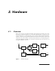
Table Of Contents
- 1. Introduction
- 2. Hardware
- 3. The A431 Radio Module
- 3.1. About the A431 Radio Module
- 3.2. Functional description
- 3.3. Manufacturing Issues
- 3.3.1. Marking and labeling issues
- 3.3.2. Alignment Range and Switching Range
- 3.3.3. Tuning Procedure
- 3.3.4. Setting Up the Default Parameters
- 3.3.5. Definitions
- 3.3.6. Test Equipment Settings
- 3.3.7. Trimming Elements
- 3.3.8. Adjusting the Receiver Front End
- 3.3.9. Adjusting the VCOs
- 3.3.10. Adjusting the Crystal Reference
- 3.3.11. Checking the Receiver Parameters
- 3.3.12. Checking the Transmitter Parameters
- 3.3.13. Data Transfer Check
- 3.6. Frequency Reference Specifications
- 3.7. A431 Module’s Photographs
- 4. Software

4
Alignment Range and Switching Range __________________________________________________ 30
Tuning Procedure _____________________________________________________________________ 31
Setting Up the Default Parameters ______________________________________________________ 31
Commands valid for all bands ____________________________________________________ 32
Commands required for band 1 __________________________________________________ 32
Commands required for band 2 __________________________________________________ 32
Commands required for band 3 __________________________________________________ 32
Commands required for band 4 __________________________________________________ 32
Definitions ___________________________________________________________________________ 33
Test Equipment Settings _______________________________________________________________ 34
Network Analyzer (HP 8712 or equivalent)_____________________________________________ 34
Service Monitor (Rohde & Schwarz CMS50 or equivalent) _______________________________ 34
Trimming Elements ____________________________________________________________________ 35
Adjusting the Receiver Front End _______________________________________________________ 35
Adjusting the VCOs ___________________________________________________________________ 36
Adjusting the Crystal Reference _________________________________________________________ 37
Checking the Receiver Parameters ______________________________________________________ 37
Checking the Transmitter Parameters ____________________________________________________ 37
Data Transfer Check ___________________________________________________________________ 38
PCB Parts Placement_________________________________________________________ 39
Bill of Materials (A431) _______________________________________________________ 41
Frequency Reference Specifications ___________________________________________ 45
A431 Module’s Photographs _________________________________________________ 46
Software ______________________________________________________49
Short Description____________________________________________________________ 49
Tasks _______________________________________________________________________ 49
Controlling the Unit__________________________________________________________ 50
Serial Communication Protocol _________________________________________________________ 50
General Format of a Command _________________________________________________________ 50
General Format of an Answer___________________________________________________________ 51
Commands___________________________________________________________________________ 51
CMDS _____________________________________________________ 51
TIME _____________________________________________________ 51
SR ____________________________________________________________________________ 52
BL ____________________________________________________________________________ 52
FREQ _________________________________________________________________________ 53
DATA _________________________________________________________________________ 53
INFO _________________________________________________________________________ 54
RX ____________________________________________________________________________ 55