
User's Manual

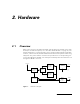
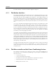
Table Of Contents
- 1. Introduction
- 2. Hardware
- 3. The A431 Radio Module
- 3.1. About the A431 Radio Module
- 3.2. Functional description
- 3.3. Manufacturing Issues
- 3.3.1. Marking and labeling issues
- 3.3.2. Alignment Range and Switching Range
- 3.3.3. Tuning Procedure
- 3.3.4. Setting Up the Default Parameters
- 3.3.5. Definitions
- 3.3.6. Test Equipment Settings
- 3.3.7. Trimming Elements
- 3.3.8. Adjusting the Receiver Front End
- 3.3.9. Adjusting the VCOs
- 3.3.10. Adjusting the Crystal Reference
- 3.3.11. Checking the Receiver Parameters
- 3.3.12. Checking the Transmitter Parameters
- 3.3.13. Data Transfer Check
- 3.6. Frequency Reference Specifications
- 3.7. A431 Module’s Photographs
- 4. Software

9
2. Hardware
2.1. Overview
Most of the electronics (including the A431 radio module) are situated on the main
board (for the A431 description, see “The A431 Radio Module” on page 27). The
main board (Figure 1) contains the radio unit, a low-speed and a high speed modem
interface, a microcontroller, RS-485 and RS-232 interfaces and a power conditioning
subsystem. The power and the serial lines are provided over a corresponding con-
nector (4-pin Binder for RS-485 or D-sub 9 pin for RS-232), while the antenna is fed
through a 50
Ω
TNC connector.
Figure 1.
A440 Block Diagram.
A431 Radio
Antenna
µController
Modem
Interface
Power
Conditioning
System Supply
Power
Module
Low Speed
Modem
Interface
High Speed
Level
Shifter
RS485/
RS232
Interfaces
Serial