
Datasheet

AddOn Computer Phone: 877.292.1701
Page 1 of 10
10GB-SR-SFPP-AO
ENTERASYS, 10GBASE-SR SFP+ MMF
850NM 300M REACH LC
10GB-SR-SFPP-AO
10Gbase SFP+ Transceiver
Features
• Compliant to SFP+ Electrical MSA SFF-8431
• Compliant to SFP+ Mechanical MSA SFF-8432
• Multi-rate compliance for Ethernet and Fiber Channel
• Transmission distance up to 300m (OM3 fiber)
• Sub watt power consumption: 0.65W (typ.)
• 0°C to +70°C case operating temperature range
• Laser Class 1 IEC / CDRH compliant
• RoHS 6/6 compliant
• Compliant with product safety standards
Product Description
The 10GB-SR-SFPP-AO is a multipurpose multi-rate optical transceiver module for
transmission at 850nm over multimode fiber. Supporting Ethernet and Fiber Channel
standards make it ideally suited for 10GB data communication and storage area network
applications. Its sub watt power consumption and its excellent EMI performance allow
system design with high port density. The small form factor integrates an 850nm vertical
cavity surface emitting laser (VCSEL) in an LC package and a PIN receiver. Addon
Computer Peripheral’s module is lead free, RoHS compliant and is designed and tested
in accordance with industry safety standards.
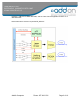
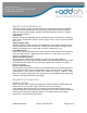
Functional Description
The Transceivers convert information from electrical to optical format, and back again, at
different data rates depending upon the chosen standard. The transmit path consists of
an AC coupled 100 ohm differentially terminated driver coupled to a highly reliable
850nm VCSEL. The laser output may be disabled by pulling the TX_DISABLE line high.
The laser is also disabled if this line is left floating, as it is pulled high inside the
transceiver. The SFP+ MSA (Multiple Source Agreement) defines two RATE_SELECT
lines, one for the transmitter (pin 9) and one for the receiver (pin 7). Depending upon the
transceiver application, the transmitter RATE_SELECT line can switch between1 GBd
and 10 GBd.
The receiver path consists of a ROSA (receiver optical sub-assembly) for optical
electrical conversion, followed by a limiting amplifier to boost the electrical signal. A
LOSS_OF_SIGNAL (LOS) status line is provided to facilitate easy link detection.
Depending upon the transceiver application, optimum receiver bandwidth may be
configured using the receiver RATE_SELECT pin: for Ethernet applications to switch