eP Pow werS Switch 8XM RR2 Us ser gu uide Version 09 9/2009 www w.neol.
© Copyright by NEOL S.A.S - 4 Rue Nationale, 67800 BISCHHEIM, France Printed in France All rights reserved. No part of this documentation, accompanying software or other components of the described product may be reproduced or transmitted in any form or by any means, electronic or mechanical, including photocopying and recording, for any purpose other than the personal use of the purchaser without the express written permission of NEOL S.A.S.
CONTENTS SAFETY INSTRUCTIONS: To be read before use! ...................................................................................... 3 1. DESCRIPTION .......................................................................................................................................... 4 1.1 Diagram ............................................................................................................................................... 4 1.2 Package list ......................................
SAFETY INSTRUCTIONS: To be read before use! NOTE • The ePowerSwitch devices can only be installed by qualified people with the following installation and use instructions. The manufacturer disclaims all responsibility in case of a bad utilization of the ePowerSwitch devices and particularly any use with equipments that may cause personal injury or material damage. • This equipment is designed to be installed on a dedicated circuit that must have a circuit breaker or fuse protection.
1. DESCRIPTION ePowerSwitch*8XM is a power control unit with a built-in Web server, an Ethernet and a RS232 connection. It enables to control the power supply of 8 power outlets through an Ethernet connection. The number of controlled power outlets can be extended up to 136 by cascading up to 16 ePowerSwitch 8XS to the Master. It supports a maximum load of 2x10A through 2 separate power inputs. This high security unit offers HTTPS protocol with Web browsers that support SSL version 2 or 3.
100 (LED) Off = 10 Mbits/sec connection On = 100 Mbits/sec connection RS232 (SUB-D 9F Connector) Serial port RS232 with DB-9 female connector Pinout 2 = TxD 3 = RxD 5 = Gnd xBus The RJ45 connector is used for cascading ePowerSwitch devices and xBus peripherals Maximal TOTAL line length: 200 meters Term (RS485 Termination DIP Switch) The xBus interface (RS485) has built-in termination resistors. To enable these resistors slide the two DIP Switch to the ON position (down).
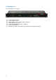
The back panel of the ePowerSwitch 8XM Power outlets (Group B) Power outlets (Group A) Power outlets 1 – 4 230 VAC max 10 Amp Power outlets 5 – 8 230 VAC max 10 Amp Power input B Power input A 230 VAC – 10 Amp 230 VAC – 10 Amp 6
1.2 Package list The following items are included: 7 1 ePowerSwitch 8XMR2 19" 1 power adapter 12 VDC 2 power cables, 230 V / 10 Amp, length 1.80 Meters 1 RJ45 M/M cable, 2 Meters 1 serial cable SUB-D 9 points M/F, 1.
2. INSTALLATION Remark: Make sure that the ePowerSwitch 8XM is powered off. Connection instructions 1. Use a shielded RJ45 network cable to connect your ePowerSwitch 8XM to the network. 2. Use appropriated three-wire power cords (two poles plus ground) to connect your electrical devices to the ePowerSwitch 8XM unit. 3. Plug the 2 power cables into 2 grounded sockets. The power supply LED of group A and of group B light on to confirm that power is on. 4.
3. CON NFIGUR RATION To use the e ePowerSwitch 8XM on your networrk, you must first configurre its network parameters s. Ask your network ad dministrator for f the param meters to use e. There are three metho ods to configu ure the netwo ork paramete ers of the eP PowerSwitch 8XM: 3.1. Con nfiguratio on throug gh the LA AN using the t Finde er program m It is the simplest and fastest confiiguration me ethod if you use u Window ws as operating system.
DHCP: Check this box is you want to obtain the IP address, the subnet mask and the default gateway for your ePowerSwitch 8XM via DHCP. Use of DHCP (Dynamic Host Configuration Protocol) requires a DHCP host to be set up on the network. IP Address: IP address of the ePowerSwitch 8XM, default is 192.168.100.200. Subnet Mask: Subnet Mask of the ePowerSwitch 8XM, default is 255.255.255.0. Gateway: Generally the address of your router, default is blank. DNS 1: Primary DNS (Domain Name Server), default is blank.
3.2. Con nfiguratio on throug gh an RS2 232 Terminal conn nection 1. Use the e provided RS232 R cable e to connect the ePowerrSwitch 8XM M to an availa able serial port p of your PC. 2. Run a Terminal T pro ogram such as a Windows HyperTermin nal. 3. Configu ure the appro opriate serial port @ 9.60 00, n, 8, 1 an nd no flow co ontrol. 4. On you ur computer, press until the e menu appe ears on your screen. 5.
3.3.1. Ge eneral / IP P configura ation This page enables you u to define all the IP parameters of the e ePowerSw witch 8XM. DHCP Clie ent enabled: Check thiss box is you want to obttain the IP address, a the subnet mask and the de efault gateway for your ePowerSw witch 8XM via a DHCP. Facctory default setting for th his option is disabled. d Use of DH HCP (Dynam mic Host Co onfiguration n Protocol) requires a DHCP hostt to be set up on the network.
HTTP Port: Port number: default is 80 (HTTP). Standard HTTP port is 80. Standard HTTPS port is 443. LOGOUT: Click "Logout" at the bottom of the page to exit the session without saving changes. DISCARD CHANGES: Click "Discard Changes" at the bottom of the page to discard all the changes you have made on this page. APPLY CHANGES: Click "Apply Changes" at the bottom of the page to save changes.
3.3.2. Ge eneral / Sy ystem time e The system m time of the e ePowerSwitch 8XM is used u for sync chronizing sccheduling acctions and to timestamp SNMP trap ps, Syslog in nformation, e-mails e and internal logs.. The system m time can be e set manua ally with the browser time of the connected c computer or can be auto omatically syynchronized with one or o two NTP timeserverrs. S Time e: Current System This field shows s the cu urrent system m time of the ePowerSwittch 8XM.
3.3.3. Ge eneral / SM MTP You can setup s the eP PowerSwitch h*8XM to se end the logs s to an ema ail account a and report all a activities triggered by b the rules defined d by th he administra ator. e you u will need a SMTP serrver on the network an nd you will h have to con nfigure the To send e-mails, following parameters s: SMTP ena abled: Check thiss box if you want w the ePo owerSwitch 8XM 8 to be ab ble to send e--mails.
3.3.4. Ge eneral / SN NMP The ePow werSwitch 8X XM provides a built-in SN NMP (Simple e Network Management M Protocol) ag gent, which enables yo ou to manage the ePowe erSwitch 8XM M through SN NMP-based network n man nagement sys stems. The ePowerSw witch 8XM MIB file enable es to remote ely read out the t status off all power ou utlets and the values of all sensorss (temperatu ure, humidityy, ambient lig ght).
3.3.5. Ge eneral / To ools This page enables you u to: - download d and save th he current se ettings of you ur ePowerSw witch 8XM on n your PC, - upload an existing co onfiguration file f to your eP PowerSwitch h 8XM, - restore th he factory se ettings, - download d the ePowerSwitch 8XM M MIB file on your PC. Save: Click this button b to savve the curren nt system setttings onto yo our local hard d drive.
3.3.6. Se ettings / Accounts A This page is used to crreate, activatte, deactivate e, modify and delete up to t 255 accou unts. ate or deactivvate an account, check or o uncheck th he corresponding checkbo - To activa ox. - To modiffy an account, click on "E Edit" next to the correspon nding accoun nt. - To delete e an existing account, clicck on "Delete e" next to the e correspond ding account. - To create e an accountt, click on "Ad dd a New Acccount" on th he right side of o the page.
Groups: This field is used to add or remove groups to the current account. To add Groups to the current account, press the Ctrl key and click on the displayed Groups. The selected Groups are marked dark blue and their IDs are listed at the right side of the Groups field. This field appears only if you have already created at least one group (Settings/Groups Tab). Device: In this drop-down list, choose a device from which you want to add Inputs or Outputs to the current account.
3.3.7. Se ettings / Groups G This page is used to create, c modify and delette groups off power outle ets which ca an be contro olled by the ePowerSw witch 8XM. This T function nality is particularly usefful if you ha ave to contro ol the powerr supply of devices using u redund dant power supplies. You Y can cre eate groupss including several pow wer outlets distributed d on several ePowerSwitc e ch 8XS devicces. e an existing group, click on "Delete" of the corres sponding devvice.
LOGOUT: Click "Logout" at the bottom of the page to exit the session without saving changes. DISCARD CHANGES: Click "Discard Changes" at the bottom of the page to discard all the changes you have made on this page. APPLY CHANGES: Click "Apply Changes" at the bottom of the page to save changes.
3.3.8. Se ettings / Peripherals s The Periph herals page is used to en nable and co onfigure the xBus x periphe erals which h have been co onnected to the ePowe erSwitch 8XM M. This page e is also veryy useful to giive an overvview of all the e peripherals s which are or have be een connecte ed to the ePo owerSwitch 8XM.
Problem / Troublesho ooting y If you u choose an ny setting th hat is alread dy in use by b another xBus x periph heral connec cted to the ePowe erSwitch 8XM XM, an addre ess conflict occurs o and the t correspo onding Edit a and Info sym mbol of the previo ous connecte ed peripherall will be repla aced by a ye ellow warnin ng triangle.
3.3.8.1. Settings S / Peripherals P - ePowerS Switch 8XM M This page enables to label the device power supply s inputs s, the 8 digittal inputs an nd 4 outputs located on the I/O Exxtension Mod dule (option) and the 8 power outlets s of the ePow werSwitch 8X XM. Names of up to 32 alphanume eric characte ers in length are supportted and appe ear in log file es, Syslog m messages, SNMP S traps and Emailss to avoid co onfusions. 1. Open you y browser and log in to o the Adminisstrator's Page e, (ex.
ID: The ePowerSwitch 8XM automatically creates an ID Code to clearly identify each device and each input. • M0 identifies the ePowerSwitch 8XM device, • PW followed by "A", "B" or "X" identifies power supply input A, B and auxiliary power input, • DI followed by 1 to 8 identifies the Digital Inputs of the I/O Extension Module (option), • EM identifies the I/O Extension Module (option), • O followed by 1 to 8 identifies the power outlets.
3.3.8.2. Settings S / Peripherals P - ePowerS Switch Sate ellite Up to 16 ePowerSwittch*8-port orr 1-port can be attache ed to the eP PowerSwitch**8XM to rem motely turn electrical devices d on/offf or reboot them. You can connect c an ePowerSwitc e ch 1XS, 8XS S or 8XS /32 2 to the RJ4 45 connectorr on the ePo owerSwitch 8XM or behind b an xBus periph heral alread dy connecte ed to the ePowerSwitc e ch 8XM (Da aisy Chain Connection).
werSwitch iss properly co onnected to the ePowerSwitch 8XM it will be au utomatically recognized If the ePow ur of the corresponding and displa ayed on this page p after a delay of up to 60 second ds. In this ca ase, the colou Edit and In nfo symbol iss red. The Perip pheral page e is not auttomatically refreshed, so you need to refresh it by clicking the periphera al TAB again (or push [F5] or prress on you ur keyboard d if you us se Internet Explorer or o Mozilla Firefox).
ID: The ePow werSwitch*8X XM automa atically crea ates an ID Code to clearly identify each connected ePowerSw witch Satellite e, its power input(s) and its i power outtlet(s).
Name: In this field, enter the name you want to give to the selected ePowerSwitch. The name can be from 1 to 32 characters long and can contain alphanumeric characters. Analog Inputs: Only for Satellite 8XS /32 Name: In this field, enter the name you want to give to the two current inputs A and B. The name can be from 1 to 32 characters long and can contain alphanumeric characters. Unit: In this field enter the unit of measurement you want to be displayed.
3.3.8.3. Settings S / Peripherals P - Analog in nputs Up to 32 temperature, temperature e and humidity, temperatture and ambient light se ensors can be b attached to the ePo owerSwitch 8XM 8 to monittor environme ental conditio ons. t e and IR proximity se ensors can be attache ed to the ePowerSwitc ch 8XM to Only 16 temperature monitor te emperature change an nd detect prresence of a target. Th he IR proxim mity sensorr acts as a digital inp put like the DIM D module e (see § 3.3.8 8.4.2).
erly connecte ed to the eP PowerSwitch h 8XM it will be automa atically recog gnized and If the sensor is prope e after a dela ay of up to 60 0 seconds. In n this case, the t colour of the correspo onding Edit displayed on this page and Info syymbol is red.. The Perip pheral page e is not auttomatically refreshed, so you need to refresh it by clicking the periphera al TAB again (or push [F5] or prress on you ur keyboard d if you us se Internet Explorer or o Mozilla Firefox).
Sensor ID D: The ePowerSwitch 8XM automaticcally creates an ID Code to t clearly ide entify each co onnected sen nsor. f followed by a number bettween 1 and 32 identifies s each tempe erature senso or, • T • TH followed f by a number bettween 1 and 32 identifies s each humid dity sensor, • TA followed f by a number bettween 1 and 32 identifies s each ambie ent light senssor. Sensor Na ame: In this field, enter the e name you want to give e to the sele ected senso or.
3.3.8.4. Settings / Peripherals - Digital Inputs Up to 16 x Digital Input Modules, Push Buttons or Temperature and Proximity sensors can be attached to the ePowerSwitch 8XM to monitor environmental conditions. You can connect them the RJ45 connector on the ePowerSwitch 8XM or behind an xBus peripheral already connected to the ePowerSwitch 8XM (Daisy Chain Connection). An I/O Extension Module is also available to connect 8 dry contact inputs and 4 relay outputs to the ePowerSwitch 8XM (ref. I/O EXT MOD). 3.
ooting Problem / Troublesho y If you choose anyy setting tha at is alreadyy in use by another a Digital Input Mo odule connec cted to the erSwitch 8XM XM, a conflict occurs and d the corres sponding Ediit and Info ssymbol of th he previous ePowe connected Digital Input Module e will be cha anged to blac ck. In that ca ase, disconne ect your lastt connected Digitall Input Module, remove e its power adapter(s), change the DIP switch h settings to o solve the addresss conflict an nd reconnectt it again.
Name: In this field, enter the name you want to give to the Digital Input Module. The name can be from 1 to 32 characters long, and can contain alphanumeric characters. Power Supplies: In this field, enter the name you want to give to the two power supplies “PWA” and “PWB”. The name can be from 1 to 32 characters long, and can contain alphanumeric characters. Digital Inputs Name: In this fields, enter the name you want to give to each Digital Input.
3.3.8.4.2. Temperature and proximity sensors Up to 16 temperature and proximity sensors can be attached to the ePowerSwitch*8XM to monitor temperature change and detect presence of a target The IR proximity sensor acts as a digital input like the Digital Input Module or the Push Button. You can connect a sensor to the RJ45 connector on the ePowerSwitch 8XM or behind an xBus peripheral already connected to the ePowerSwitch 8XM (Daisy Chain Connection).
ure or modifyy the settingss of a sensorr, click on the e correspond ding "Edit" bu utton in the Peripherals P To configu page. A new page ap ppears, allow wing you to set s all the pa arameters off the temperrature & proximity (TP) sensors. Sensor ID D: The ePowerSwitch 8XM automaticcally creates an ID Code to t clearly ide entify each co onnected sen nsor. owed by a nu umber betwe een 1 and 16 6 identifies ea ach proximityy sensor.
3.3.8.4.3. Push Button Up to 16 Push buttons can be attached to the ePowerSwitch 8XM to trigger manually pre-programmed actions. You can connect a Push Button to the RJ45 connector on the ePowerSwitch*8XM or behind an xBus peripheral already connected to the ePowerSwitch 8XM (Daisy Chain Connection). To connect a Push button to the ePowerSwitch 8XM, use following procedure: 1.
ure or modiffy the setting gs of the Pu ush Button, click c on the correspondiing "Edit" bu utton in the To configu Peripherals page. A new n page ap ppears, allow wing you to set all the parameters p o of the conne ected Push Buttons. ID: The ePowerSwitch 8XM automaticcally creates an ID Code to t clearly ide entify each Push button.
3.3.8.5. Settings / Peripherals - AC Current Probe Up to 16 AC Current probes can be attached to the ePowerSwitch*8XM to monitor the current consumption of an electrical device (PC, server, light, printer…) and trigger actions if predefined limits are exceeded. You can connect an AC Current probe to each of the RJ45 connector on the ePowerSwitch*8XM or behind an xBus peripheral already connected to the ePowerSwitch*8XM (Daisy Chain connection).
C Current Prrobe, click on n the corresp ponding "Ediit" button in 4. To configure or modify the settings of an AC ge. A new pa age appears,, allowing you to set all th he paramete ers of the con nnected AC the Perripherals pag Currentt Probe. ID: t clearly ide entify each C Current Probe e. The ePowerSwitch 8XM automaticcally creates an ID Code to f by a number bettween 1 and 16 identifies s each curren nt probe • CP followed • I1 identifies the current analog input.
3.3.8.6. Settings / Peripherals - Energy Meter Up to 16 EnergyMeters can be attached to the ePowerSwitch 8XM to monitor the energy consumption (kWh) and the current consumption (Amp RMS) of eight electrical devices (PC, server, light, printer…) and trigger actions if predefined limits are exceeded. The EnergyMeter is also able to monitor the Input voltage of both 16 Amps power inputs.
4. To configu ure or modiffy the setting gs of the En nergyMeter, click c on the correspondiing "Edit" bu utton in the Peripherals page. A ne ew page app pears, allowin ng you to sett all the param meters of the e Analog Inp puts. This page is used to co onfigure the connected EnergyMeter. E . ID: t clearly ide entify each Energy Meter. All the ID The ePowerSwitch 8XM automaticcally creates an ID Code to ed to identifyy an Energy Meter M start with w the chara acters "EM" followed f by a number.
3.3.9. Se ettings / Rules R Rules are used to con ntrol actions according to t a specific event. For example, yo ou can define a rule to switch a po ower outlet OFF O and sen nd an alert message m usin ng different methods m like email, SNMP P or Syslog when a temperature, humidity, h am mbient light or o current exceeds a predefined valu ue or when a contact is open. o "Delete" of o the corresponding rule e.
A total of 255 rules can be created and there are 6 different types of rules: 1. Schedule Rule: This rule can be used to trigger user-specified actions according to a defined time table. 2. Ping Monitoring Rule: This rule is used to control actions according to the response to a Ping command. 3. Scan Monitoring Rule: This rule is used to control actions according to the response to a Scan command. 4.
3.3.9.1. Settings S / Rules R - Sche edule Rule e This rule can c be used to t trigger use er-specified actions acco ording to a de efined time ta able. The schedule rule is weekdayy based and the adminisstrator can de eclare, for ea ach weekdayy, a start time e, an end tim me and after what time the rule shou uld be repea ated. The sched dule rule can also be use ed to send sttatus informa ation or sensor values on n specified weekdays w at regular inte erval.
Stop Time Defines what time the rule ends. - End Time must be greater than or equal to Start Time. - If the rule has to be executed only once at the selected weekday, enter the same value for Start Time and End Time. - If the rule has to be executed 24 hours at the selected weekday, Start Time must be 1 minute later than EndTime. Applicable weekday Defines which day(s) the rule has to be executed.
Syslog / Trap / Mail Message: This field appears only if you have already specified at least one destination Syslog Server (Misc/Log Settings Page), one destination SNMP Server (General/SNMP Page) or a destination SMTP Server (General/SMTP Page). Up to 255 characters may be entered in this free text field. The text will appear in the Syslog, the Trap and the e-mails.
3.3.9.2. Settings S / Rules R - Ping g Monitorin ng Rule This rule can c be used to check if a computer or o any IP de evice is connected to the network. It sends ping packets an nd listens forr replies from m the specificc host. If the host doesn't reply, the e ePowerSwitc ch 8XM can automatica ally switch th he powered device d off an nd after a sp pecified delayy, switch it again on (for details see Ping & Sca an Method).
Number of unsuccessful Requests before Action: In this field, define the number of Ping commands to be sent to the IP device before executing the actions. The number can be set between 1 and 65535 seconds. Delay before First Request after Power up: In this field, define the time in seconds before restarting the monitoring after the reboot action. The delay can be set between 30 and 65535 seconds.
LOGOUT: Click "Logout" at the bottom of the page to exit the session without saving changes. DISCARD CHANGES: Click "Discard Changes" at the bottom of the page to discard all the changes you have made on this page. APPLY CHANGES: Click "Apply Changes" at the bottom of the page to save changes.
3.3.9.3. Settings S / Rules R - Scan n Monitorin ng Rule This rule can c be used to t check if a specific prottocol is availa able on a server (for example HTTP, FTP, Telnet, SM MTP, POP...)). If the conne ection is posssible, ePowe erSwitch 8XM M knows that a server program is running the ere. If the co onnection is not n possible, ePowerSwittch 8XM can n automaticallly switch the e powered device off and, after a specified delay, switch it again on (fo or details see e Ping & Scan Method).
Interval between Requests: In this field, define the delay between the scan commands sent to the IP device. The delay can be set between 30 and 65535 seconds. Number of unsuccessful Scan Commands before Action: In this field, define the number of Port scanning commands to be sent to the IP device before executing the actions. The number can be set between 1 and 65535 seconds.
Syslog / Trap / Mail Message: This field appears only if you have already specified at least one destination Syslog Server (Misc/Log Settings Page), one destination SNMP Server (General/SNMP Page) or a destination SMTP Server (General/SMTP Page). Up to 255 characters may be entered in this free text field. The text will appear in the Syslog, the Trap and the e-mails. LOGOUT: Click "Logout" at the bottom of the page to exit the session without saving changes.
3.3.9.4. Settings S / Rules R - Pow wer Supply Monitoring g Rule This rule can c be used d to monitor the status of o the 2 pow wer supplies of the ePow werSwitch 8X XM and the power sup pplies of conn nected periph herals like eP PowerSwitch h 8XS and Digital Input M Modules. Rule ID: The ePow werSwitch 8X XM automaticcally createss an ID Code e to clearly identify each h rule. All the e ID Codes used to ide entify rules start s with the letter "R" folllowed by a number n from m 1 to 255.
A character between brackets can follow this ID Code: - The "X" character means that the corresponding peripheral is physically not connected. - The "!" character means that the corresponding peripheral is physically connected but not activated. If you want to activate it, go to the "Settings/Power Outlets" tab. - The " " character (blank) means that the corresponding satellite is physically connected and activated.
Syslog / Trap / Mail Message: This field appears only if you have already specified at least one destination Syslog Server (Misc/Log Settings Page), one destination SNMP Server (General/SNMP Page) or a destination SMTP Server (General/SMTP Page). Up to 255 characters may be entered in this free text field. The text will appear in the Syslog, the Trap and the e-mails.
3.3.9.5. Settings S / Rules R - Digital Input Monitoring M Rule R This rule can c be used d to monitor the status of o an electrical contact (a a door conta act, a smoke e contact, a proximity sensor, s a pussh button) an nd to initiate different actions if the co ontact status has changed. Rule ID: The ePow werSwitch 8X XM automaticcally createss an ID Code e to clearly identify each h rule. All the e ID Codes used to ide entify rules start s with the letter "R" folllowed by a number n from m 1 to 255.
In the second drop-down list, choose the Input you want to monitor. The ePowerSwitch 8XM uses ID Codes to clearly identify each Input: • DI1 to DI4 for the digital inputs of the ePowerSwitch 8XM, • PS followed by a number for the IR proximity sensor inputs, • DI followed by a number for the digital inputs of a DIM module, • SP followed by a number for a short push on the push buttons, • LP followed by a number for a long push on the push buttons. Action if contact...
Syslog / Trap / Mail Message: This field appears only if you have already specified at least one destination Syslog Server (Misc/Log Settings Page), one destination SNMP Server (General/SNMP Page) or a destination SMTP Server (General/SMTP Page). Up to 255 characters may be entered in this free text field. The text will appear in the Syslog, the Trap and the e-mails.
3.3.9.6. Settings S / Rules R - Analog Input Monitoring M Rule This rule can c be used to monitor an a Analog In nput value (temperature, humidity, am mbient light, current....) and perforrm actions when the pred defined value e is exceeded d. Rule ID: The ePow werSwitch 8X XM automaticcally createss an ID Code e to clearly identify each h rule. All the e ID Codes used to ide entify rules start s with the letter "R" folllowed by a number n from m 1 to 255.
- The "X" character means that the corresponding sensor is physically not connected. - The "!" character means that the corresponding sensor is physically connected but not activated. If you want to activate it, go to the "Settings/Power Outlets" tab. - The " " character (blank) means that the corresponding sensor is physically connected and activated. According to the device you use, choose the Analog Input in the second Drop-Down (temperature, humidity, light, current, energy...).
Send Syslog Messages: This type of action appears and can be configured only if you have already created at least one destination Syslog Server (Misc/Log Settings Tab). Check this box if you want to send a message to a Syslog server. In the following drop-down lists choose the facility and the severity of the message to send. The address of the Syslog server has to be defined in the "Log Settings Page".
3.3.10. Misc M / Con ntrol Panell This page is very help pful for the ad dministrator because it gives g a comp plete overvie ew of all the peripherals which are currently connected orr have been n connected to the ePo owerSwitch 8 8XM. At a glance, g the administra ator can checck the statuss of the pow wer supplies of the ePow werSwitch 8X XM and the connected Peripherals.
3.3.11. Misc M / Rule e Panel This page shows all the rules the e administrattor has creatted and activated. The rrules which have been executed can also be e highlighted d in differentt colours ac ccording to the t emergen ncy of the action. a The highlight colours can be b customized during the creation of the t rule (Setttings/Rules P Page). For supervvision purposse, the administrator can n create spe ecial accountts which disp play only som me specific rules.
3.3.12. Misc M / Log The log file f keeps a running lo og of eventss and activ vities occurriing on the device. The e logs are automatica ally cleared when w the devvice is reboo oted. The file will display up u to 2048 re ecent logs.
3.3.13. Misc M / Log Settings This page allows you to t configure the t logs. The e Log file is used u by the system s to record actions s, warnings, errors and d problems. It is often quite q useful to t discover the causes of tricky pro oblems. The messages recorded in the log file f and sen nt as copy to a Syslog g server are e classified into 8 seve erity levels (Emergenccy, Alert, Crittical, Error, Warning, W Nottice, Informational and De ebug).
4. POW WER OU UTLET CONTR C ROL AND D PERIP PHERAL LS STAT ATUS 1. Start yo our Web brow wser and typ pe the IP add dress of yourr ePowerSwittch 8XM. The browser diisplays the authenttication dialo og box. 2. Enter a user name and its corre esponding pa assword. The e status of th he ePowerSw witch 8XM is displayed.
d lisst, choose the power con ntrol unit you want to conttrol or the pe eripheral for which w you 3. In the drop-down want to o know the sttatus. If you lo og in as systtem administtrator, you wiill be able to:: - contro ol all the pow wer outlets an nd all the pow wer outlet groups of the connected c eP PowerSwitch h devices, - displa ay the instantt values of alll the conneccted sensors (temperature, humidity, ambient light), - displa ay the status of all digital inputs.
5. APPENDIX 5.1. Sending status information and sensor values using rules The administrator can create rules (see Settings/Rules) to trigger actions and send personalized messages in form of Syslog messages, SNMP traps or emails when an event occurs. Moreover, the administrator also has the possibility to complete his messages with status information of an input (a power supply or a door contact for example) or the value of a sensor (a temperature sensor for example).
5.2. Ping and Scan Methods ePowerSwitch 8XM has two methods to check whether an IP equipment (PC, server, router, Webcam...) is still alive: Address Pinging: The first method uses the well-known Ping command whereby a request is sent to a specific IP address. The Ping command, which is an echo request, enables you to determine through an ICMP protocol (Internet Control Message Protocol) if an IP device is available on the network.
5.3. Technical Data Network standards: IEEE 802.3, 10 / 100 BASE-T Network protocols: TCP/IP, HTTP/HTTPS Network connection: RJ-45 connector for STP CAT5 Max. network cable length 100 meters Serial connection: RS232, SUB-D 9 female SSL Technology: Version 2 and 3 Operating temperature: 0°C to +40°C Operating humidity: 10% to 80% RH (not condensing) Dimensions (LxDxH): 170 x 110 x 42 mm Weight: 0,63 kg Approvals: CE, EN55022 & EN55024 5.4.
5.5. Syslog Messages: Severity Level Definitions The Emergency level is the most severe type of message generated by ePowerSwitch 8XM and the Debug severity level is the least severe one.
Severity Level 6, Informational: The following messages appear at severity 6: - System has been started - Date & Time have been synchronized to a Network Time Server - User "name" : Outlet (number) of Master M0 has been switched ON - User "name" : Group (number) has been switched ON - Dry Contact Input (number) has been opened - Dry Contact Input (number) has been closed - Dry Contact Output (number) has been opened - Dry Contact Output (number) has been closed - Mail "subject" has been sent to "name" - Ses
STATEMENT OF CONFORMITY STATEMENT OF CONFORMITY NEOL S.A.S. declares that this equipment is in compliance with the Electromagnetic Compatibility Directive 89/336/EEC and the Low Voltage Directive 73/23/EEC Application of Council Directives: 89/336/EEC, 92/31/EEC, 73/23/EEC, 93/68/EEC Standards to Which Conformity declared:EN 60950, EN 55022, EN 55024 Manufacturer's Name and Address: 4 Rue Nationale NEOL S.A.