
Specifications


AdderLink X-Series Installation and Use Page 47
controls which of the colours (on all AdderLink products, switch bank A is BLUE, B is
RED and C is GREEN).
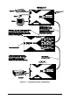
To determine which switch bank controls the delay of which colour you must first
install the skew compensator as shown in figure 11. Set all the switches to the OFF
position. Now set all the switches in one bank (e.g. A1 to A4) to the ON position and
observe the change to the video picture. The delayed colour should appear as a
shadow on the right hand side of white objects that are on a dark background. This
shadow may best be observed of you have a picture with white objects set against a
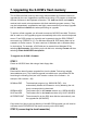
black background. For example, if you create a picture similar to that shown below in
a drawing package such as Paint then the delayed colour will be seen on the right
hand side of the white square.
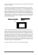
Once you have determined which set of switches controls which colour you can
switch all the switches OFF and observe the picture. Remember that the picture is
made up from red, green and blue colour signals. Use a test pattern similar to that
shown above and observe the component colour that is most delayed (i.e. the one
that appears as a shadow after a white image on a black background). Leave all the
switches associated with this colour in the OFF position and start to add delays to
the OTHER colours by setting some of their associated switches to the ON position.
Observe the changes to the picture after you change the switches. Switches 1 and 2
each introduce a 10 nanosecond delay. Switch 3 introduces a 5 nanosecond delay
and switch 4 introduces a 2.5 nanosecond delay.
A process of trial and error is required to find the best switch settings.