ADT22XA Series Multifunction Process Calibrators Users Manual Version: 1303V01 © 2011 Additel Corporation. All rights reserved. Specifications are subject to change without notice.
CONTENTS ADT22XA Series Calibrators ....................................................................................................................................... 1 1. Specifications ...................................................................................................................................................... 2 2. Safety Information .........................................................................................................................................
8.1 Basic Mode ................................................................................................................................................................. 24 8.2 Measuring .................................................................................................................................................................. 25 8.2.1 Millivolts Measurement ...................................................................................................................
8.3.8 Frequency Source.................................................................................................................................................. 40 8.3.9 Pulse Source .......................................................................................................................................................... 40 8.3.10 Resistance Simulation ..............................................................................................................................
9.5.1 Alarm Settings ....................................................................................................................................................... 52 9.5.2 Screen Settings ...................................................................................................................................................... 52 9.5.3 Auto Power Off ...................................................................................................................................
11.4.1 Loop Test ............................................................................................................................................................. 71 11.4.2 PV Zero Trim ........................................................................................................................................................ 72 11.4.3 PV Calibration.................................................................................................................................
ADT22XA Series Calibrators TheADT22XA series calibrators areultra‐compact, rugged, durable and easy‐to‐use hand‐held devices for sourcing, simulating, measuring temperature, electrical signals and pressure. With HART communication capability, the calibratoris ideal for calibrating, maintaining and troubleshooting HART instruments.
1.
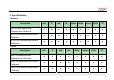
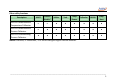
Other utility functions Description HART Pressure Module* Utilities Task Loop Power ADT221A Multifunction ○ ○ ● ● ● Temperature Calibrator ADT222A Multifunction ○ ● ● ● ● Process Calibrator ADT223A Documenting ● ● ● ● ● Process Calibrator Note:●: Available, ○: Unavailable, *CDP Series Intelligent Digital Pressure Modules.
2. Safety Information ◆ ◆ ◆ ◆ Follow all equipment safety procedures. Do not operate the calibrator within a hazardous atmosphere (explosive gases, vapors and dust). Do not throw the battery into fire or make electric short circuit. Use the power adapter supplied by Additel only. Please refer to the CDP user instruction for safety when the CDP pressure module is being used.
3. Standard Accessories and Optional Accessories 3.
3.2 Optional Accessories ◆ ◆ ◆ ◆ ◆ ◆ Intelligent digital pressure modules ( for the ADT222A, ADT223A only). Pressure module connection cable (only when pressure module is purchased). Factory calibration certificate for pressure module. Factory calibration certificate for multifunction calibrator. USB to RS232 (DB‐9 Male) adapter (only when software is purchased). Cold Junction compensation kits (including TC plug and compensation cable, please refer to chapter 5.
4. Cautions ◆ Do not connect the test leads before toggling to another measurement or sourcing function. ◆ Do not touch the metal parts in the test lead interface to avoid introducing errors. ◆ Never apply more than 30V between any two electrical jacks (except when measurement is 30V range). ◆ To avoid water penetration into the calibrator, regular cleaning and maintenance is recommended. ◆ Only use the power adapter supplied by Additel to recharge battery.
5. Technical Index 5.1 Working Environment Temperature: (‐10 to 50)℃. Relative humidity: <90%(Non‐condensing). Atmosphere pressure: (86 to 106) kPa. 5.2 Storage Environment Temperature: (‐20 to 60)℃. Relative humidity:<90% (Non‐condensing). 5.3 Electrical Parameters Power supply: polymer Li‐ion rechargeable battery or 10VDC adaptor. Charge mode: specified 10VDC adaptor (charging time is less than 4 hours).
Thermocouple measure and simulating (for cold junction and automatic compensation modes): flat mini‐size socket. Charger connection: standardφ2.1mm charger jack. RS232 interface: standard RS232‐DB9 socket. Pressure module: five‐pole circular push‐pull connector. RS232 parameter: baud rate is 2400, 4800, 9600 or 19200, data bits is 8, stop bits is 1, address is from 1 to 121.
Pulse Limit Switch 0 to 999999 1 N/A If the switch has detective voltage, its range is +3V to +24V Note 1: When ambient temperature is (‐10 to 15℃and 25 to 50℃), temperature coefficients are: (1) Voltage, current measurement: ±(0.001%RD+0.0015%FS) /℃. (2) 2‐wire, 3‐wire, 4‐wire resistance measurement: ±(0.002%RD+0.001%FS)/℃. Note 2: Input features: (1) Voltage measurement: input impedance>1MΩ, overvoltage of ports is ±300VDC.
Electrical Signal SourceSpecifications: (working environment: 20±5℃, accuracy for one year) Table5‐2 Function Range Resolution Accuracy ‐10.000 to 75.000 mV 1μV 0.02%RD+0.005%FS 0 to 12.0000 V 0.1mV 0.02%RD+0.005%FS 0 to 22.000 mA 1μA 0.02%RD+0.005%FS 1 to 400.00 Ω 10mΩ 0.02%RD+0.005%FS 1 to 4000.0 Ω 100mΩ 0.03%RD+0.01%FS Frequency 0 to 50000.0 Hz 0.1Hz 0.005%RD+0.002%FS Pulse 0 to 999999 1 N/A DC24V N/A N/A 0.
(5) (6) (7) (8) (9) 0.6mA).For (1Ω to 400Ω) range, 1mA driving current is recommended, and for (400Ω to 4000Ω) range, 0.1mA driving current is recommended. Frequency, pulse source: Source square wave with (50±10)% duty cycle, amplitude range 2V to 12V, amplitude accuracy 3%FS. Loop 24V DC power: The maximum load current is 50mA, ripple <50mV.
Simulating Thermocouple Source&using Thermocouple to Measure Temperature Accuracy. (Working temperature: 20℃±5℃) Table5‐3 Thermocouple Measurement and Source accuracy Measure and Simulate S R B K Standard IEC 584 IEC 584 IEC 584 IEC 584 Accuracy (℃) Temperature Range (℃) ‐50 to 1768 ‐50 to 1768 0 to 1820 ‐270 to 1372 Measure Source ‐50 to 400 1.0 1.1 400 to 1000 0.6 0.6 1000 to 1768 0.7 0.8 ‐50 to 200 1.4 1.4 200 to 500 0.6 0.
N E J T C D IEC 584 IEC 584 IEC 584 IEC 584 ASTM E988 ASTM E988 ‐270 to 1300 ‐270 to 1000 ‐270 to 1200 ‐270 to 400 0 to 2315 0 to 2320 ‐250 to ‐200 1.5 1.6 ‐200 to ‐100 0.5 0.6 ‐100 to 1300 0.4 0.5 ‐250 to ‐200 0.6 0.7 ‐200 to ‐100 0.3 0.3 ‐100 to 0 0.2 0.2 0 to 700 0.2 0.3 700 to 1000 0.2 0.4 ‐210 to ‐100 0.3 0.3 ‐100 to 1200 0.3 0.4 ‐250 to ‐200 0.8 0.9 ‐200 to 0 0.4 0.4 0 to 400 0.2 0.
G L U ASTM E1751 DIN43710 DIN43710 0 to 2315 ‐200 to 900 ‐200 to 600 2000 to 2320 0.9 1.3 0 to 200 2.4 2.4 200 to 400 0.5 0.5 400 to 1400 0.4 0.5 1400 to 2315 0.7 1.0 ‐200 to ‐100 0.2 0.3 ‐100 to 400 0.2 0.2 400 to 900 0.2 0.3 ‐200 to 0 0.4 0.4 0 to 600 0.2 0.
Simulating RTD Source and using RTD to Measure Temperature Accuracy. (Working temperature: 20℃±5℃) Table5‐4 RTD Measurement and Source accuracy Measure and Simulate Pt10(385) PT100(385) Pt100(3916) Pt200(385) Accuracy (℃) Standard IEC 751 IEC 751 IEC 751 IEC 751 Temperature Range (℃) ‐200 to 850 ‐200 to 850 ‐200 to 850 ‐200 to 850 Measure 2W、3W Measure 4W Source ‐200 to 200 0.65 0.60 0.65 200 to 600 0.82 0.72 0.82 600 to 850 0.96 0.82 0.
Pt500(385) Pt1000(385) IEC 751 IEC 751 ‐200 to 850 ‐200 to 850 ‐200 to 200 0.20 0.16 0.36 200 to 600 0.32 0.22 0.54 600 to 850 0.40 0.27 0.67 ‐200 to 200 0.1 0.05 0.25 200 to 600 0.2 0.10 0.42 600 to 850 0.27 0.14 0.54 Cu10(427) IEC 751 ‐100 to 260 ‐100 to 260 0.61 0.56 0.61 Cu50(385) IEC 751 ‐50 to 150 ‐50 to 150 0.17 0.13 0.17 Cu100(385) IEC 751 ‐50 to 150 ‐50 to150 0.12 0.09 0.
6. Summary The ADT22XA series calibrators are high performance instruments, designed for the calibration of heat engineering secondary instruments, pressure gauges and DCS systems. The hand‐held calibrator is highly stable and reliable, it’squite suitable for calibration, maintenance and troubleshooting. Features: 1. Measure mA, millivolts, volts, ohms, frequency, pulses, limit switch, RTDs and thermocouples. 2.
7. Structure and Functions 7.
7.
interface RS232 interface Rechargeable jack Communicating with PC Charger connection Note:To view the position of jacks1 ‐ 12, please refer to section 7.1.
7.3 Key Functions Table7‐2 No. Name 1 Power key 2 Starts HART communications function (only HART is available). 3 Selects the millivolts, volts, pulse or frequency measurement or the sourcing function. 4 Selects the resistance or limit switch test measurement or selects the resistance source. 5 Selects the RTD or thermocouple measurement or the sourcing function. 6 Selects mA (current) measurement or the sourcing function.
11 12 Leaves the current page, cancel the choice or operation. In calculator page, provides clear functions (C). Confirms the choice or operation. In calculator page, provides the equals arithmetic operator (=). Activates the measurement or sourcing display area, fine tunes the source value in Basic Mode. Select the item from the drop down list. In calculator page, provide arithmetic functions (+ ‐ ÷ ×). 13 14 Softkeys Performs the function defined by the context label.
8. Basic Operation 8.1Basic Mode When the device is entered into startup page, it always appears the Basic Mode.The main screen displays Voltage in the measurement display area and Voltage in the source display area (as Figure 8.1). When returning from higher level operations(Setup, Task, Measuring options, Sourcing options and so on), the calibrator will also return to the Basic Mode with last configured measurement and source.
8.2 Measuring In the Basic Mode (as Figure8.1), if measurement is active, you can press switch keys ( , , , , )to pop up relevant measurement items list. If source is active, you can press a switch key twice to pop up relevant measurement items lists. You can select a measurement from the list. To change any of measurement parameters, the measurement must be in active state.
2. If measurement is active, press once, otherwise press twice. 3. Press the navigation keys Up/Downto select the second item from the pop‐up list, and then pressEnter orDone to change the measurement. 4. To improve measurement precision, you can short the volts input, then press Zero to clear the measured value. 8.2.3 Frequency Measurement Proceed as follows to measure frequency: 1. Figure8.3 shows the frequency measurement connections. 2.
change the measurement or press Options to show pulse counting setup interface. 4. In Pulse Counting, press Options to show pulse counting setup interface. Here you can change the pulse trigger edge mode. 5. After finishingthe pulse counting, you can press Zero to reset the counter, then to start a new pulse counting. 8.2.5 Resistance Measurement Figure 8.4 Pulse Counting Figure 8.
1. Figure 8.5 shows the resistance measurement connections. 2. If measurement is active, press once, otherwise press twice. 3. Pressthe navigation keys Up/Down to select the first item (range 0 to 400Ω) or second item (range 0 to 4000Ω) from the pop‐up list, then press Enter or Done to change the measurement or press Options to show resistance measurement configuration interface. 4.
the measurement. 4. To improve measurement precision, you can short the current input, and then press Zero to clear the measured value. Figure 8.6 Limit Switch Test Figure 8.7 Current Measurement 8.2.
When a pressure module is connected, the pressure module icon will appear in the status bar and beep at the same time. Figure 8.8 shows thepressure measurement connections. Proceed as follows to measure pressure: 1. If measurement is active, press once, otherwise press twice. 2. Press the navigation keys Up/Down to select the first item from the pop‐up list, then press Enter or Done to change the measurement. 3.
junction adjacent to the thermocouple jack.when using external reference mode, The fixed reference temperature value(range: ‐10 to 50 ℃ )must be entered manually before thermocouple measuring. Figure 8.9 shows the thermocouple measurement connections. To measure temperature by using thermocouple simulation, proceed as follows: 1. If measurement is active, press once, otherwise press twice. 2.
8.2.10 RTD Measurement (Temperature) The calibrator supports11 common RTDs shown in Table 5‐4. In addition, calibrator accepts 10custom RTDs.to add a custom RTD please refer to 9.4.3. The calibrator accepts RTD measurement inputs in two‐wire, three‐wire, or four‐wire connections as shown Figure 8.10. The four‐wireconnection can provide the highest measurement precision. When using RTD input to measure temperature, proceed as follows: 1.
8.3 Sourcing In the Basic Mode (as Figure8.1), if the source is active, you can press ( , , , , ) which will pop up the relevant source item list. If measurement is active, you can press the desired switch key twice.Also, by pressing the navigation keys Up/Down, you can also focus on the source area. 8.3.
To exit fine tuning, you can pressEsc or Enter key. Notes: If there is no operation within 15 seconds, the calibrator will exit fine tuning automatically. You cannot change thefine tuning if the source value exceeds the output range, the calibrator will beep. 8.3.3 Reset the source value In the Basic Mode, for volts, millivolts, frequency, resistance and current source items, the calibrator offers the reset function.
Stepping supports three modes: an engineering unit, scale and step points. Note: In the engineering unit and stepping mode, the transfer functions default setting is always linear. Only for auto step, the run mode and step time are valid. The range of the Step time is 1 to 3600 seconds. Figure 8.12 Stepping Results To use manual stepping, proceed as follows: 1. If necessary, press the navigation keysUp/Downuntil source is active. 2.
End Value(in units) Step Mode: Eng. Units, Scale or Step Points Step Size (Scale or Count, according to the Selection of Step Mode) Trans Function: Linear or Square Root 3. To complete the step settings, press Enter orDone, then the calibrator will Return to the Basic Mode and show the main screen. 4. PressManual to start manual stepping.Andthe softkey label will changes to Next. 5. Now you can adjust the source value in steps by pressing Enter orNext. 6.
main screen. 4. Press Auto to beginautomatic stepping, and the softkey label will change to Pause. 5. Press Pause to pause automatic stepping. The softkey label will change to Resumeat the same time.You can press Resume to continue automatic stepping. If you want to exit automatic stepping, press Esc orExit. 8.3.5 Ramping the source value In the Basic Mode, the calibrator offersthe source value ramping. Ramping can smoothly and continuously increase or decrease the source value.
1to 3600 seconds. Figure 8.14 Ramping Results Proceed as follows to ramp: 1. If necessary, press the navigation keys Up/Down until source is active. 2.
Run Mode(Repeat or Single shot) 3. To completethe ramp settings, press Enter orDone, then the calibrator will return to the Basic Mode and show the main screen. 4. Press Enteror Start to begin automatic ramping, and the softkey label will change to Pause. 5. Press Pause to pause automatic ramping, and the softkey label will change to Resumeat the same time.Press Resume resuming the automatic ramping. If you want to exit automatic ramping, pressEsc or Exit. 8.3.
application 8.3.8 Frequency Source Proceed as follows to source frequency: 1. If source is active, press once, otherwise press twice. 2. Press the navigation keys Up/Down to select the third item from the pop‐up list, then press Enter or Done to change the source to frequency or press the Options softkey to show the frequency source setup interface. In the frequency source setup interface; you can set the amplitude. 3.
5. If you want to stop sourcing, press Stop, and the softkey label will change back to Start, you can resume sourcing pulse too. 8.3.10 Resistance Simulation Proceed as follows to simulate resistance: 1. If source is active, press once, otherwise press twice. 2. Press Up/Down to select the first item (range 1to 400Ω) or second item (range 1 to 4000Ω) from the pop‐up lists, and then press Enter or the Done to change the source to resistance simulation. 3.
switch source to current. 4. When sourcing current with internal power, the 24VDC loop power states must remain as ON. If the 24VDC power state is OFF, it will be automatically turned back ON states after switching source to current with internal power. 5. Refer to the sections 8.3.1, 8.3.2, 8.3.3, 8.3.4 or 8.3.5, select a method to change the source value according to your need. 8.3.12 Pressure source (only available for pressure module) Proceed as follows to pressure source: 1.
7. Using external special pressure generatorto adjust the pressure value. 8.3.13 Thermocouples Simulation Refer to Table 5‐3 for data about thermocouple types included in the calibrator. Proceed as follows to simulate a thermocouple: 1. If source is active, press once, otherwise press twice. 2.
Detector) types by calibrator supported. Proceed as follows to simulate an RTD: 1. If source is active, press once, otherwise press twice. 2. Press the navigation keys Up/Downto select the second item in the pop‐up lists, and then press Enter orDone to switch source to RTD simulation or press Options to show RTD simulation setup interface. In RTD simulation setup interface, you can set the RTD sensor type and temperature units (℃, K, ℉). 3.
9. Setup To personalize your calibrator, use utilities and get help, etc. you can press Setup in Basic Mode to enter the Setup page (as Figure 9‐1). In Setup page, you can press the navigation keys to move the cursorand press Enter or theSelect to choose the sub item. The following sections will introduce you to use Setup. 9.
value, sourcingvalue, reference junction compensation temperature (for thermocouples), and loop power status and system time. To enter the Snapshot List in the Snapshot Management page, press Enter or Select,and all snapshots in the calibrator’s memory will be presented in the Snapshot List. You can recall the snapshot by its name or index. The calibrator can store 100 snapshot files. If there is not enough memory space, you must erase previous snapshots.
9.4.2 Simulate Transmitter The transmitter is a device which can measure temperature, electrical signals and pressure, etc. Generating a signal according to the measurement imposed. The calibrator can simulate a transmitter.It can measure RTDs, thermocouples, frequency, volts, mA, ohms and pressure (when the pressure module is connected), and output mA and voltssignal. Before starting the transmitter simulation, you should ensure the external device is available.
Figure 9.2 Simulate Transmitter Quantity Figure 9.3 Simulate Transmitter Range Caution: To avoid possible damage to the instrument connected to the output signal loop, remember to scale the output signal of the simulation.
9.4.3 Custom RTDs Library The calibrator can measure temperature with most RTDs. But sometimes there is a need to support non‐standard RTDs and Standard PRTs (standard platinum resistance thermometers). The calibrator allows you to input the customized values, so you can measure temperature usingevery kind of RTDs and Standard PRTs.
interpolation equations. The calibrator uses the first and last deviation function for the calculation for SPRT.If you use other temperature ranges, and can be assigned to zero (i = 7, 8, 9, 10, 11). The table 9‐1 list the sub ranges, required calibrated in the NIST SPRT Laboratory. Table 9‐1 Temperature range(℃) Required Fixed Points Deviation Function -189.3442 to 0.01 Ar TP, Hg TP, TPW 0 to 29.7646 TPW, Ga TP ∆ 1 0 to 156.5985 TPW, GaTP,In FP ∆ 1 0 to 231.
9.4.4 Thermal Calculator The built‐in utility Thermal Calculator can help you convert temperature vs. resistance (RTDs), and temperature vs. millivolts (thermocouples). Select Thermal Calculator from the Utilities list box and press EnterorSelect, then the Thermal Calculator page will appear. On this page, you can choose RTD or TC (thermocouples) from the Thermo Type drop down list. The sensor type drop down list includes all the available sensors.
Pump the pressure to your target value until the pressure is stable (To avoid damaging the pressure module from overpressure, never apply pressure above the rated maximum printed on the pressure module). Press Enteror the Start to starttesting. When the test starts, the test time escapes second by second. The leak test will be stopped when the test time is zero. Then the test results will appear in the Report group box.
automatically if there are no operations within the period. You can select Never to disable the backlights auto‐off. 9.5.3 Auto Power Off You can set the power off automatically after the specified timeout period.If you do not want to power off automatically, set this to Never. Note: If the calibrator is connecting to a pc, auto power off will not work. 9.5.
1. 2. 3. 4. Enter the calibration password: 316. Select anitem from the calibration list: measurement, source and pressure module. Connect to a more precise, higher‐standardized unit, and finish the calibration step by step. You can restore the factory calibration data by pressingRestore 9.7 24V dc Loop Power The calibrator supplies an internal loop power at 24V dc. You can choose an item from the dropdown list: ON and OFF.
10. Taskand AsCal 10.1 What is the AsCal? AsCal is a typical calibration process including as‐found and as‐left, and Task is the calibration procedure of a UUT (Unit Under Test). The ADT22XA calibrators can perform AsCal, calculate errors (Zero Error and Span Error), display results in the memory and highlight the out‐of‐tolerance points. You can download tasks and upload the results with special software. The software can generate reports and certificates for the tasks.
Figure 10.
10.2 Creating a new Task There may be no tasks in the Calibrator's database when you want to run a task. You can create a new task via "New Task Wizard" or download them from the special calibration software. According to different instruments,there are five types of task: RTDs (Resistance Temperature Detector), TC (Thermocouples), Loop Instruments, Flow (Delta‐Pressure and Flow Meters), Pressure Instruments. To start your task management pressTask in Basic Mode.
The Output Quantity includes the corresponding common fields similar with the Input Quantity. The same additional fields are also available for the Output Quantity (as shown in Figure 10.3). Note: Do not forget to check the transfer function setting at the bottom of the page. Figure 10.2 Task UUT Input Data Figure 10.
Editing UUT Calibration Data Then we should set the tolerance and the calibration set points (as shown in Figure 10.4). The tolerance should besetcorrectly. Otherwise it will causeundesired result. Change the calibration points (2 to 11) by press the navigation keysLeft/Right, the default set points will be calculated automatically. The default set points are typical values for calibration.
10.4 Select a Task to Be Calibrated The already calibrated task is marked with "√" in the list of tasks (as shown in Figure 10.5). If there is no task in thecalibrator’s database,you can download them from the calibration software or create tasks in the calibrator (refer to previous section. You can select one of the available tasks by pressing Enter or Select Figure 10.
The detail data will be shown before you run thetask. If you want to change the parameters of the task, you can edit it by pressing Edit(as shown in Figure 10.6). If the task has been calibrated, the parameters cannot be edited, and then press "Save As" tosave it as a new oneand the parameters will be editable. You can press the navigation keysLeft/Right to switch the content in this page. Before starting a task, you should ensure the external device is available.
The Calibration Method page will appear when the task can be calibrated both manually and automatically (as shown in Figure 10.7). About Automatic Calibration Automatic calibration is possible when the calibrator is able to generate/simulate the UUT’s input signal, and measure the UUT’s output signal. The Step Time (set point delay) setting is in use only when the Calibration Method is set to Automatic. It determines theinterval between the two calibration points.
The Calibration Mode page will appear if the UUT is indicator or recorder (as shown in Figure 10.8). About Reverse Calibration Adjust the output signal of the calibrator until the reading of the UUT displays a nominal set point, then record the reading from the calibrator. The calibrator will calculate the UUT's theoretical reading accordingly. In most cases, the reverse calibration is a very practical method, which eliminates the trouble of manual recording.
After calibration method/calibration modeconfiguration, you will enter the AsCal running page (assuming you have selected manual calibration). You can switch to the graph viewing modeor data viewingmode by pressing Data/Graph(as shown in Figure 10.9 and Figure 10.10). In the graph mode, you can see a visual reading of the trend of errors. In the data mode, you can see the detail data and errors. On the top of the error graph chart, you can see the maximum tolerance and set point values.
AsCal calibration. If you do not want to save the calibration results and continue to calibrate the UUT, you can press ReCal to return to the AsCal running page. If you want to accept the calibration results, and save the data. Press the Save then select the save options. If the UUT is a HART‐Transmitter, the Adjust will be enabled. Press Enter or Finish, thenfinish the whole AsCal calibration. Figure 10.
10.5 Viewing the Task Results On the Task List page, select a calibrated task (marked with "√") and press Enter or Select The overview of the task will appear. The maximum error (As Found and As Left) and parameters of the Task will display on this page (as shown in Figure 10.11). You can re‐calibrate the UUT by pressing Enter or AsCal as described in the previous section.
11. HART Communication (only HART is available) 11.1 Brief and note Thecalibrator is a secondary master device, and has no impact on the normal communication between a primary master device and a HART device. The jacks of HART (refer to Table7‐1) have a built‐in HART resistor. This HART resistor is optional and its rate current is 44mA. Note 1: The calibrator can measure current only with a range of ‐30 to 30mA.
11.2 Connect to a HART Device To start communication with a HART device, you can press HART then the calibrator will prompt you to select the HART resistor. Figure 11.1 shows the connection with internal built‐in HART resistor. Figure 11.2 shows the connections with an external HART resistor. Figure 11.1 the connection with internal built‐in resistorFigure 11.2the connection with external resistor To insure the connection is correct refer to Figure 11.1 or 11.2.
1. After you have selected internal or external resistor prompted by the calibrator, press Enter key or the Select softkey to start pollingthe HART devices. 2. The calibrator will try to poll from address 0 to 15. If there is HART device be found at address 0, polling will be Figure 11.3 HART Device Information Figure 11.
aborted immediately and show the HART device list. Otherwise calibrator will continue searching from address 1 to 15, and automatically stop polling at address 15. In the period of polling, you can press Stop tostop polling. If more than one hart device is found, calibrator will show the HART devices list, otherwise calibrator will prompt you whether to poll HART device again. A maximum of 15 HART devices can be supported. 3.
this interface you can view more HART Process Variablesincluding primary variable (PV), rang (%), PV current value (AO), loop current (CA), thesecondary variable, the third variable, and the fourth variable, and their values are continuously updated. PV, %,AO, and CA are selectable; you canchoose a process variable and return to the Communication Interface (Figure 11.4). 11.
Loop Test. 3. If the Loop Test is successfully executed, the PVAO at the top of the interface will show the specified value, the calibrator will show the measured current value in the middle of the interface. Otherwise a popup will indicate the “HART device not found”. 11.4.2 PV Zero Trim The PV Zero Trim operation sends a command to the transmitter to set its PV zero. To perform a PV Zero Trim operation, proceed as follows: Figure 11.
1. In the HART diagnostic and service interface, choose PV Zero Trim from list, then you can press Enter or Select to Figure 11.8 HART PV Zero Trim Figure 11.9 HART PV Calibration Setting start the PV zero operation. The screen will ask you to confirm the PV zero (As shown in Figure 11.8). 2. Press OK to confirm or Cancel.
11.4.3 PV Calibration Adjust the HART transmitter’s PV LRV and URV to get the coherence between the standard source range and digital analog output (AO). To perform the PV Calibration operation, proceed as follows: 1. In the HART diagnostic and service interface, choose PV Calibration from list, then pressEnteror Select to show the PV Calibration Setting Interface (Figure 11.9). 2. In the SettingInterface, you can set the sensor type and the range of the transmitter.
(Figure 11.10 and Figure 11.11). Once the calibration is complete (Figure 11.11), the PV range adjustment information will be displayed at the bottom of the interface. You can decide whether to adjust PV range. To reject, pressEsc or Reject;to adjust, press Enter orAdjust. 11.4.4 Special Calibration Special Calibration is very similar to the PV Calibration operation.
trim, then you can press Enter or Done to display the Output Trim interface (as shown in Figure 11.12). 3. In the Output Trim interface, press Enteror Trim to execute the output point adjustment. The trim value can be fetched by pressing Fetch, or it can be inputted manually. 4. If Output Trim is successfully executed, the calibrator will goes back to the Output Trim point selection interface. You can repeat steps 2 and 3 to start another Output Trim. Figure 11.
11.5 HART Setup Whenthe measurement is active in HART communication mode, pressSetupto show the HART setup interface.The calibrator provides five setup functions (refer to table 11‐1).
Device Info. HART Output HART Info.
11.6 Exit HART connection If the measure item is switched to another item, the calibrator will exit the HART communication mode. HART communication will be aborted and the HART icon in the status bar will be hidden.