HD-SD DOWN CONVERTER BOARD HKDW-702 INSTALLATION MANUAL 1st Edition (Revised 2)
! WARNING This manual is intended for qualified service personnel only. To reduce the risk of electric shock, fire or injury, do not perform any servicing other than that contained in the operating instructions unless you are qualified to do so. Refer all servicing to qualified service personnel. ! WARNUNG Die Anleitung ist nur für qualifiziertes Fachpersonal bestimmt. Alle Wartungsarbeiten dürfen nur von qualifiziertem Fachpersonal ausgeführt werden.
Section 1 Installation 1-1. HKDW-702 Configuration The HKDW-702 consists of the following: . DC-110A board (1) . Shield plate (1) . Screw P2 x 4 (2) . Precision screw P1.4 x 3.5 (3) . VIDEO OUT assembly (1) . Installation Guide (1) . Installation Manual (1) In addition to the Installation Manual, the following manuals are available. . HDW-750 Operation Manual (Supplied with HDW-750) This manual is necessary for application and operaion of HDW-750. Part number: 3-205-316-0X .
1-3. Confirming the AT ROM Version 1-3. Confirming the AT ROM Version Installation of the HKDW-702 requires that the ROM (IC38) on the AT-143 board of the HDW-750 is version 1.32 or higher. Confirm the ROM version before starting installation as follows. 1. Turn on the power of the HDW-750. 2. While pressing the rotary encoder, turn on the MENU ON/OFF switch to open the top menu. MENU ON/OFF switch OFF ON/SEL STATUS OFF ON CANCEL/PRST ESCAPE MENU 3.
1-4. Opening and Closing the Inside Panel 1-4. Opening and Closing the Inside Panel Opening the Inside Panel n Be sure to turn off the POWER switch, unplug the AC power cord or remove the battery before starting the following procedure to prevent the inside of the unit from damage. 1. Loosen the four screws (with drop-safe) and open the inside panel in the direction of the arrow. m . Folding the flexible card wire connected to the FP121 board shortens the life of the flexible card wire significantly.
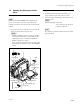
1-5. Installing the VIDEO OUT Assembly 1-6. Installing the HKDW-702 (DC-110A Board) 1-5. Installing the VIDEO OUT Assembly 1. Remove the inside panel. 2. Remove the two screws (P2 x 4) and remove the CN BOX sub panel. 3. Attach the VIDEO OUT assembly with the two screws (P2 x 4) by routing the coaxial cable through the groove. m . When installing the VIDEO OUT assembly, route the coaxial cable through a groove. .
1-7. Setting the SD VBS SETUP Level 1-7. Setting the SD VBS SETUP Level Perform the following procedure only when the VBS SETUP level is desired to be set to 7.5%. Switch description MENU ON/OFF switch MENU CANCEL/PRST/ ESCAPE switch OFF ON/SEL STATUS OFF ON CANCEL/PRST ESCAPE MENU Rotary encoder STATUS ON/ SEL/OFF switch 1. Open the inside panel and set the switch S1-1 on the AT-143 board to ON. 2. Turn on the main power. 3.
1-7. Setting the SD VBS SETUP Level 7. 8. 9. 10. Turn off the main power. Open the inside panel and set the switch S1-1 on the AT-143 board to OFF. Turn on the main power. While pressing the rotary encoder, set the MENU ON/OFF switch to ON and open the TOP menu. 11. Select the FILE menu and let the ALL FILE display appear on screen. Press the rotary encoder. 12. Move the cursor (→) to 3SEC CLR PRESET and press the rotary encoder to ON.
The material contained in this manual consists of information that is the property of Sony Corporation. Sony Corporation expressly prohibits the duplication of any portion of this manual or the use thereof for any purpose other than the operation or maintenance of the equipment described in this manual without the express written permission of Sony Corporation. Le matériel contenu dans ce manuel consiste en informations qui sont la propriété de Sony Corporation.
HKDW-702 (UCJ) J, E 3-205-558-03 Sony Corporation B&P Company Printed in Japan 2002.