CITIZEN User's Manual Model : iDP-3410 Dot Matrix Printer Rev.1.00 Newly issued on 20.Oct.1998 Japan CBM Corporation Information Systems Div.
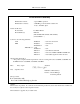
iDP-3410 User’s Manual Declaration of Conformity Manufacturer’s Name : Manufacturer’s Address Declare the Product Product Name Model Number(s) : Japan CBM Corporation : CBM Bldg., 5-68-10, Nakano, Nakano-ku Tokyo, 164-0001, Japan Dot Matrix Printer iDP-3410 (iDP-3410R/P, iDP-3410S/C, iDP-3410T/I) (S.NO.
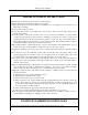
iDP-3410 User’s Manual IMPORTANT SAFETY INSTRUCTIONS •Read all of these instructions and save them for future reference. •Follow all warnings and instructions marked on the product. •Unplug this product from the wall outlet before cleaning. Do not use liquid or aerosol cleaners. Use a damp cloth for cleaning. •Do not use this product near water. •Do not place this product on an unstable cart, stand or table. The product may fall, causing serious damage to the product.
iDP-3410 User’s Manual grundsätzlich Stecker aus der Steckdose ziehen. Keine Flüssigkeiten oder Aerosolreiniger benutzen. Nut mit einem feuchten Tuch abwischen. •Der Drucker darf nicht in der Nähe von Wasser aufgestellt werden. •Drucker nicht auf einem unstabilen Wagen, Stand oder Tisch aufstellen. Der Drucker könnte herunterfallen und dabel beschädigt werden. •Schlitze und Öffnungen im Gehäuse, in der Rückwand und im Boden dienen der Belüftung.
iDP-3410 User’s Manual IMPORTANT: This equipment generates, uses, and can radiate radio frequency energy and if not installed and used in accordance with the instruction manual, may cause interference to radio communications. It has been tested and found to comply with the limits for a Class A computing device pursuant to Subpart J of Part 15 off FCC Rules, which are designed to provide reasonable protection against such interference when operated in a commercial environment.
iDP-3410 User’s Manual
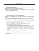
iDP-3410 User’s Manual SAFETY PRECAUTIONS ----- BE SURE TO OBSERVE In order to prevent hazards to an operator or other persons and damage to property, be sure to observe the following precautions. _ The following describes the degrees of hazard and damages that can occur if the given instructions are neglected or the equipment is incorrectly operated. WARNING Negligence of this precaution may result in death or serious injury.
iDP-3410 User’s Manual WARNING ! _ Never handle the equipment in the following manners, as it may break, become out of order, or overheat causing smoke and resulting in fire or electric shock. If the equipment is used in an abnormal condition, such as when broken, then problems, smoke emission, abnormal odor/noise, and fire can result. If an abnormal condition exists, be sure to turn off the power, disconnect the power plug from a plug socket, and contact our dealer.
iDP-3410 User’s Manual PRECAUTIONS FOR INSTALLATION • Do not use or store the equipment in a place exposed to fire, moisture, or direct sunlight, or in a place near a heater or a thermal device where the prescribed operating temperature and humidity are not met, or in a place exposed to much oil, iron powder, or dust. The equipment may become out of order, emit smoke, or catch fire.
iDP-3410 User’s Manual PRECAUTIONS FOR HANDLING Do not handle the equipment in the following manners, because problems may result. • Do not use a power supply other than the specified AC adapter. • Do not print when there is no recording paper or ink ribbon set in the equipment. The print head may be damaged • Be careful not to drop foreign substances, such as clips, pins, and screws, into the main body. • Do not spill any liquid or spray any chemical-containing liquid over the equipment.
iDP-3410 User’s Manual DAILY MAINTENANCE • Prior to starting maintenance work, be sure to turn off the main body. • Use a dry soft cloth to wipe off stains and dust from the surfaces of the main body case. For severe soiling, dip the cloth in water and wring it, for wiping off the soil. Never use organic solvents, such as alcohol, thinner, trichlene, benzene, ketone, or chemical dusters. • If the equipment is contaminated with paper powder, use a soft brush to clean it.
iDP-3410 User’s Manual CONTENTS 1. OUTLINE........................................................................................................................................................ 16 1.1 Features................................................................................................................................................................ 16 1.2 Unpacking............................................................................................................................
iDP-3410 User’s Manual 10.3 Input and Output Signals ..................................................................................................................................... 41 10.3.1 Input and Output Signals.......................................................................................................................... 41 10.3.2 Data Configuration................................................................................................................................... 43 10.
iDP-3410 User’s Manual <<< German >>> 4. BETRIEB...................................................................................................................................................... 145 4.1 Anschluß des Netzteils ...................................................................................................................................... 145 4.2 Anschluß des Schnittstellenkabels.........................................................................................................
iDP-3410 User’s Manual 1. OUTLINE This is a small-size dot impact printer developed for various data communication terminals, POS terminals, kitchen-use printers, bank card, terminals, and so on. Its abundant built-in features allow you to widely use this printer for different applications. Prior to using it, read and understand this manual thoroughly. 1.1 (1) (2) (3) (4) (5) (6) 1.
iDP-3410 User’s Manual Character Set F: International Interface CBM Mode R: Serial(RS-232C D-Sub) P: Parallel(CENTRONICS-based) STAR Mode S: Serial(RS-232C mini DIN) C: Parallel(CENTRONICS-based) ESC/POS Mode T: Serial(RS-232C D-Sub) I: Parallel(CENTRONICS-based) hExclusive AC Adapter Types and Power Cords •34AD-U (120 V 2-core cord) •34AD-E (230 V 2-core cord)
iDP-3410 User’s Manual 2.2 Basic Specifications Model iDP-3410-*F120 Item Printer mechanism Print method Print width Print head Print speed Print columns Character size Character types Line spacing Paper Ink ribbon Interface Command system Print function Input buffer Buffer backup Drawer Auto loading Paper end detection Supply voltage iDP-3410-*F230 DP-410 Series (CITIZEN) Serial dot impact method (Bi-directional print) 64 mm 9 pins Approx. 3 lines/sec.
iDP-3410 User’s Manual 2.3 Paper Specification 2.3.1 Recommended Paper •Type : Normal paper and non-carbon paper •Paper width : 76 +/- 0.5 mm •Paper thickness : Single-sheet paper --- 45∼55 kg / 1,000 sheets / 1,091 x 788 mm; Copying paper --Non-carbon paper, 1 original + 1 copy, Total thickness 0.2 mm or less •Roll diameter : φ83 mm or less •Core : φ12 mm (Inner Diameter), φ18 mm (Outer Diameter) Printing Position 2.3.3 Cutter Layout Cutting Position Approx. 20 mm 2.3.
iDP-3410 User’s Manual 3. OUTER APPEARANCE AND COMPONENT PARTS 4. OPERATION 4.
iDP-3410 User’s Manual (1)Turn off the Power switch. (2) Connect the cable connector of the AC adapter to the power connector located on the back of the printer. (3) In order to prevent disconnection of the cable connector, put it through a wire saddle, as shown in the figure below. (4) Connect the AC power cord plug to a plug socket. CAUTION : • Use only the specified AC adapter. • Use a different AC power supply from one used for any noise-generating device.
iDP-3410 User’s Manual 4.2 Connecting Interface Cable (1) Turn off the power. (Mating side included) (2) Check the top and bottom of the cable terminals, and connect to the interface connector. (3) Fix the cable terminals. •Serial Interface: Tighten screws, to fix. •Parallel Interface: Turn a stopper, to fix. (4)Connect the cable to a computer. 4.3 Connecting Drawer Kick-Out Connector (1) Turn off the power.
iDP-3410 User’s Manual 4.4 Setting the Cassette Ribbon (1) Open the printer cover. (2) If the ribbon is slackened, turn the knob in the arrow-indicated direction to give the tension to it before setting. (3) While putting the ribbon in between the head cover and platen, push the locking claws into the holder of the printer. (4) Turn the knob of the cassette ribbon in the arrow-indicated direction to eliminate slackness of the ribbon.
iDP-3410 User’s Manual 4.5 Inserting the Paper (1) Put your hands in the concave parts on both sides of the printer cover, and open it until it comes to a stop. (2) Cut the end of the paper roll at close to a right angle. CAUTION : • Be sure to use the specified paper roll. • Use of unspecified paper may adversely affect print quality, printer service life, and so on. • The printer cover is not detachable. Do not apply an excessive force beyond its stopping position.
iDP-3410 User’s Manual CAUTION : • If the paper is slack, rewind it, to remove the slack. • If the paper is set slantwise, operate the paper-free lever, to correct the paper position. • While printing, do not hold the paper. This can cause a paper jam.
iDP-3410 User’s Manual 4.6 How to Remove Remaining Paper Roll (1) Open the printer cover. (2) Pushing the paper-free lever in the arrow direction, pull out the paper roll. CAUTION : When pulling out the paper (Forward/Reverse direction), be sure to operate the paperfree lever. 4.7 Removing Paper Jam (1) Open the printer cover. (2) Cut off the paper near the paper inlet slot. (3) Push the paper-free lever in the arrow direction.
iDP-3410 User’s Manual 4.8 Operation Panel and Display of Error (1) POWER lamp(Green) Illuminated when the power is turned on. (2) ERROR lamp(Red) Illuminated when the printer is out of paper or has a printer mechanical error or communication error. •Paper end ----- If the paper runs out, the paper sensor located in the paper course near the print head detects a paper end, turning on the ERROR LED, thus stopping the printer.
Power-on iDP-3410 User’s Manual 4.9 Operation Flow at Power-on Feed SW ? Buffer data No 1 Sec. Passed Yes "Clear Data in Buffer" Yes(FEED SW) and Enlarged Red Print No 1 Sec. Passed No Yes Off Off FEED SW ? (CONTINUE) On Prints" =HexadecimalDump = Dump Mode On Input Buffer Clear Test Print Buffer Data No Yes Prints "Power Down(Data in Buffer)" in Red, Followed by Buffer Contents.
iDP-3410 User’s Manual 5. DIP SWITCH SETTING 5.1 Location of DIP Switch (1) Turn off the power. (2) Remove a cassette ribbon. The DIP switches are located as shown in the figure below.
iDP-3410 User’s Manual 5.2 DIP Switches Setting 1) DIP Switch 1 No. Function DS1-1 Auto cutter International characters DS1-2 ″ DS1-3 ″ DS1-4 DS1-5 Paper used DS1-6 CR mode DS1-7 Number of columns DS1-8 Buffer size DS1-9 Operation mode ″ DS1-10 *1, *3 : Depends on the type. *2 : Depends on the destination. International Character Selection No. DS1-2 DS1-3 Country ON Yes OFF No See the Table below 2P 1P See the Table below 42 40 6K bytes 256 bytes See the table below DS1-4 U.S.A.
iDP-3410 User’s Manual 2) DIP Switch 2 No.
iDP-3410 User’s Manual 6. PRESET JUMPER SETTING 6.1 Location of Preset Jumper (1) Turn off the power. (2) Remove a cassette ribbon. (3) Remove the top cover. The preset jumper is located as shown in the figure below. Serial Interface 6.
iDP-3410 User’s Manual 8. INPUT BUFFER BACKUP FUNCTION 8.1 Buffer Size With the DIP switch, you can set either 6K bytes or 256 bytes. DIP switch 1-8 ON → 6K bytes OFF → 256 bytes 8.2 Input Buffer Backup Even if the power is turned off or fails during the printing process, the data in the input buffer will be saved. If the power is turned on again, the printer will print a power failure mark, "==POWER DOWN==," in red and reprints the data from the beginning of the line where it left off. 8.
iDP-3410 User’s Manual 9. PARALLEL INTERFACE 9.1 9.2 Specifications •Data input system •Control signals •Applicable connectors : 8-bit parallel system (DATA1 to DATA8) : ACK, BUSY, STB, FAULT, SELECT, RESET, COMPULSION : Printer side --- 57LE-40360 (Equivalent to anphenol), Cable side --- 57-30360 (Ditto) Connector's Pin Configuration Mode No.
iDP-3410 User’s Manual 9.3 Input and Output Signals 9.3.1 Input and Output Signals (1) Input signals to the printer • DATA : An 8-bit parallel signal. (Positive logic) • STB : A strobe signal to read the 8-bit data. (Negative logic) • RESET : A signal to reset the printer from the outside.(Negative logic) (2) Output signals from the printer • ACK : An 8-bit data request signal. A pulse signal output at the end of the BUSY signal.
iDP-3410 User’s Manual 9.3.2 Electrical Characteristics (1) Input signal level All the input signals are at the TTL level. "HIGH" level : 2.0 V at minimum "LOW" level : 0.8 V at maximum (2) Output signal level All the output signals are at the TTL level. "HIGH" level : 2.4 V at minimum "LOW" level : 0.4 V at maximum (3) Input and output conditions All the input signals are pulled up at 3.3 kΩ. [Printer Side] [Host Side] All the output signals are pulled up at 3.3kΩ.
iDP-3410 User’s Manual 9.3.3 Timing Chart (1) Data input and printing timing T1, T2, T3 T4 T5 T6 : : : : 0.5 µs MIN 270 ns MAX 2.3 µs TYP 500 ms MIN (At power-on) 9.3.4 Data Receiving Control When the BUSY signal is at "LOW," the printer can receive the data from the host, but when at "HIGH," it cannot. 10. SERIAL INTERFACE 10.
iDP-3410 User’s Manual (4) Signal polarity RS-232C •Mark = Logic "1" (-3 V ∼ -12 V) •Space = Logic "0" (+3 V ∼ +12 V) (5) Received data (RXD signal) RS-232C • Mark = 1 • Space = 0 (6) Reception control (DTR signal) RS-232C •Mark : Data transfer disabled •Space : Data transfer enabled
iDP-3410 User’s Manual 10.2 Connector's Pin Configuration Mode No. 1 2 3 4 5 6 7 8 9 10 11 12 13 14 15 16 17 18 19 20 21 22 23 24 25 CBM STAR ECS/POS FG TXD RXD ← ← ← ← ← ← ← RTS GND ← PE (HI-LEVEL) FAULT RCH DSR ← GND FAULT mTXD mRXD DTR ← ← RESET Cautions: 1. An RS-232C signal is based on the EIA RS-232C. 2. When the data is not being transferred, the received data should be always maintained as a mark.
iDP-3410 User’s Manual 10.3 Input and Output Signals 10.3.1 Input and Output Signals (1) RXD This is a serial received data signal. When a framing error, overrun error, or parity error occurs, that data is printed as "?". (2) DTR When this signal is Ready, write the data or a command. If written at the time of Busy, an overrun error results, ignoring the previous data. The data can be written in the input buffer even during printing.
iDP-3410 User’s Manual (8) RCH When the printer is ready to receive, this signal is turned to Space. This signal line is the same as DTR. (9) mTXD TXD signal for the diode gate. (10) mRXD RXD signal for the diode gate. (11) FG This is a Frame Ground signal. (12) GND This is a common ground on the circuit. 10.3.2 Data Configuration t Mark b0, b1, b2, ........
iDP-3410 User’s Manual (1) Start bit After a lapse of 1/2 bit from a mark-to-space fall edge, the state is read again, and if it is a space, it is recognized as the start bit. If it is a mark, it is assumed neither the start bit nor an error, and it is attempted to detect the start bit again. (2) Data bit + parity bit The data bit and parity bit are sampled for 1 bit worth of time from the 1/2 start bit. The then state is assumed the data for the corresponding bit.
iDP-3410 User’s Manual 10.3.6 Electrical Characteristics (1) RS-232C circuit Input (RXD, DSR, mRXD) [Printer Side] [Host Side] Output (DTR, TXD, mTXD, RCH, RTS, FAULT) RXD Mark=(-8V): Stop bit Space=(+8V): Start bit Equivalent MAX232 DTR Equivalent to MAX232 Mark=(-8V): At Busy Space=(+8V): At Ready TXD Mark=(-8V): 1 Space=(+8V): 0 (2) Others •RESET •PE •GND •FG : A signal to reset the entire printer. : A signal to show that the paper has run out.
iDP-3410 User’s Manual 11. DRAWER KICK-OUT CONNECTOR AND POWER CONNECTOR 11.1 Specifications of Drawer Kick-Out Connector (1) Drawer kick-out drive signal Parallel Interface ----- Can be learned at the no. 34 pin of the interface connector Serial Interface ----- Provided with a command to learn the status in the Star and ESC/POS modes. (2) Electrical characteristics 1) Drive voltage: 24 V DC 2) Drive current: 0.8 A at maximum(Within 510 ms) 3) Switch signal: Signal level "L" = 0 ∼ 0.5 V "H" = 3 ∼ 5 V 11.
iDP-3410 User’s Manual 11.4 Specifications of Power Supply Connector This is a power connector from an exclusive AC adapter. Connector’s Pin Configuration 1 Jack used Applicable plug No. Function 1 2 +24V GND 2 : HEC0470-01-640(HOSHIDEN) or equivalent : JXP series Type-A (I.D. 2.45 mm, O.D. 5.5 mm) (HOSHIDEN) or equivalent CAUTION: • Be sure to use the specified power supply. Use of unspecified one may lead to a trouble or breakage. • Do not connect the power supply with different polarities.
iDP-3410 User’s Manual 12. MAINTENANCE AND SERVICE For the information on maintenance and service, please contact our dealer or at the following address. Northern America CBM America Corporation Service Center 365 Van Ness Way Suit 510 Torrance, CA 90501, U.S.A Other Areas Japan CBM Corporation Information Systems Division CBM Bldg., 5-68-10, Nakano Nakano-ku, Tokyo 164-0001 Japan TEL +1-310-781-1460 FAX +1-310-781-9157 TEL +81-3-5345-7540 FAX +81-3-5345-7541 13. PRINT CONTROL FUNCTIONS 13.
iDP-3410 User’s Manual 10 11 12 13 14 15 16 17 18 19 20 21 22 23 24 25 26 27 28 29 ESC ∗ n1 n2 ESC − n ESC 1 ESC 2 ESC 3 ESC C n ESC N n ESC O ESC f 1 ESC t n ESC BEL n1 n2 BEL FS SUB RS ESC R 1 ESC & 0 n1 n2 ESC % n ESC ⁄ n ESC DC3 n 30 ESC DC2 n1 n2 31 32 GS ∗ n1 n2 GS ⁄ m Specifying the bit image mode 1BH 2AH n1 n2 Specifying/Canceling the Underline 1BH 2DH n Specifying 1/9-inch line feed rate 1BH 31H Specifying 2/9-inch line feed rate 1BH 32H Specifying 1/6-inch line feed rate 1BH 33H Setting the
iDP-3410 User’s Manual XXX Shows a command.
iDP-3410 User’s Manual Details FF n [Function] n-line paper feed [Code] <0C>H n [Range] 1 ≤ n ≤ 127 [Outline] This command feeds the paper by n-lines. You can set n = 1 to 127 lines. If the print buffer contains the data, use of this command feeds the paper by n-lines after printing the data. Setting n = 0 does not feed the paper. [Function] Specifying the double width character [Code] <0E>H [Outline] The data following this command is printed doubled in the horizontal direction.
iDP-3410 User’s Manual SI [Function] Canceling the double width character [Code] <0F>H [Outline] This command cancels the double width characters set with SO. The data following this command are printed in the ordinary character width. [Function] Printing and paper feed [Code] <0A>H [Outline] If the print buffer contains the data, this command will feed the line after printing. If not, the command only feeds the line.
iDP-3410 User’s Manual mixed in one line.
iDP-3410 User’s Manual DC3 [Function] Specifying the red print [Code] <13>H [Outline] This command specifies red-color characters. All the characters in one line are printed in red by prefixing the print data with this command and sending it to the printer. When you want to use red characters, use this command for each line. CAN [Function] Canceling the print data [Code] <18>H [Outline] This command clears the print data in the lines entered prior to this command.
iDP-3410 User’s Manual ESC "∗" n1 n2 [Function] Specifying the bit image mode [Code] <1B>H <2A>H n1 n2 [Range] 1 ≤ n1 + 256 × n2 ≤ 378 [Outline] This command allows printing in the bit image mode. Divide the number of dots printed by 256 and assume its quotient to be n2 and remainder to be n1. Therefore, the number of horizontal dots will be n1 + 256 × n2. If the bit image data is entered beyond the dot positions printable in one line, the surplus data will be discarded.
iDP-3410 User’s Manual ESC "3" [Function] Setting the 1/6-inch line feed width [Code] <1B>H <33>H [Outline] This command sets the line feed width to 1/6 inch(Default). ESC "C" n [Function] Setting the page length [Code] <1B>H <43>H n [Range] 1 ≤ n ≤ 127 [Outline] Sets the 1-page length to n-lines.
iDP-3410 User’s Manual ESC "N" n [Function] Specifying the perforation skip [Code] <1B>H <4E>H n [Range] 1 ≤ n ≤ 126 [Outline] This command feeds(Skips) the lines specified with n without printing. However, you cannot specify beyond the length of one page. ESC "O" [Function] Canceling the perforation skip [Code] <1B>H <4F>H [Outline] This command cancels perforation skipping operation.
iDP-3410 User’s Manual ESC "t" n [Function] Selecting the character code table [Code] <1B>H <74>H n [Range] 0 ≤ n ≤ 255 [Outline] This command selects Page-n of Character Code Table. [Default] Depends upon DIP switch setting.
iDP-3410 User’s Manual ESC BEL n1 n2 [Function] Setting the external device drive pulse width [Code] <1B>H <07>H n1 n2 [Range] 1 ≤ n1 ≤ 127 [Outline] This command sets the power-on time to drive an external device (Cash drawer). Power-on time = n1 × 10 (ms) Delay time = n2 × 10 (ms) To actually drive the drawer, use the and commands.
iDP-3410 User’s Manual FS [Function] Driving command B drawer-1 [Code] <1C>H [Outline] This command drives the drawer connector No. 2 pin under the condition set with the n1 n2 command. SUB [Function] Driving command for drawer-2 [Code] <1A>H [Outline] As soon as this command is received, the drawer connector no. 5 pin is driven. The poweron time is 200 ms ON and 200 ms OFF stationary. The drawers 1 and 2 cannot be driven simultaneously.
iDP-3410 User’s Manual ESC "R" n [Function] Selecting the international character set [Code] <1B>H <52>H n [Range] 0 ≤ n ≤ 10 [Outline] This command selects the international characters according to the value of n. n Character Set n Character Set 0 U.S.A. 6 Italy 1 France 7 Spain 2 Germany 8 Japan 3 U.K. 9 Norway 4 Denmark I 10 Denmark II 5 Sweden [Default] Depends upon DIP switch setting.
iDP-3410 User’s Manual ESC "&" <0> n1 n2 [m0 m1 ... m5 m6 m7 m8 m9] n2 - n1 + 1 [Function] Defining the Download character set [Code] <1B>H <26>H <00>H n1 n2 [m0 m1 ... m5 m6 m7 m8 m9] n2 - n1 + 1 [Range] 32 ≤ n1 ≤ n2 ≤ 255 m0 = 0 or m0 = 128 [Outline] This command defines he download characters. n1 is a character code to start definition and n2 is to end definition, respectively. When defining only one character, set n1 = n2. You can define the ASCII codes ranging from 32 to 255.
iDP-3410 User’s Manual ESC "%" n [Function] Specifying/Canceling the download character set [Code] H <25>H n [Outline] This command selects/deselects the download character set. The download characters cannot be printed by simply defining them with the above-mentioned ESC & 0 command. To print them, send this command to the printer.
iDP-3410 User’s Manual ESC DC3 n [Function] Printing the message [Code] <1B>H <13>H n [Range] 1 ≤ n ≤ 10 [Function] This command prints a message. If the value of n is specified beyond the range, the message will not be printed.
iDP-3410 User’s Manual ESC DC2 n1 n2 [Function] Deleting the download character, message, bit image [Code] <1B>H <12>H n1 n2 [Range] 0 ≤ n1 ≤ 3 0 ≤ n2 (Specify 0 at n1 = 0) (1 ≤ n2 ≤ 10 at n1 = 1) (32 ≤ n2 ≤ 255 at n1 = 2) (Specify 0 at n1 = 3) [Outline] This command deletes the downloaded characters, message, and bit image.
iDP-3410 User’s Manual GS "∗" n1 n2 [d] n1 × n2 × 8 [Function] Defining the download, bit image [Code] <1D>H <2A>H [] n1 × n2 × 8 [Range] 1 ≤ n1 ≤ 45 0 ≤ n2 ≤ 24 Note) Take care that the number of data (n1×n2×8) is equal to or smaller than 2,048. [Outline] This command defines the download bit image having the dots specified n1 and n2. The number of horizontal dots is represented by n1 × 8 and that of vertical dots is represented by n2 × 8, respectively.
iDP-3410 User’s Manual GS ⁄ m [Function] Printing the download, bit image [Code] <1D>H <2F>H m [Range] 0 ≤ m ≤ 255 [Outline] This command prints the bit image saved in the number specified with m. [Caution] If the print buffer contains the data, this command will be ignored. If the bit image has not been saved in the specified number, this command will be ignored. Nothing is printed when m is other than 0,1,2 or 3.
iDP-3410 User’s Manual 13.2 STAR Mode 13.2.
iDP-3410 User’s Manual 44 45 46 47 48 49 FS SUB RS CAN DC3 DC1 50 ESC U n 51 52 53 54 55 56 57 ESC @ ENQ STX ETX ESC t n ESC ⁄ n ESC DC3 58 ESC DC2 n1 n2 59 60 GS ∗ n1 n2 GS ⁄ m Driving command B for drawer-1 Driving command for drawer-2 Buzzer-on Canceling the print data Setting the deselect mode Setting the Select mode Selecting the Unidirectional/bidirectional print mode Initializing the printer Enquiry Text start Text end command Selecting the character code table Defining the message Printin
iDP-3410 User’s Manual Details ESC “R” n [Function] Selecting the international character set [Code] <1B>H <52>H n [Range] 0 ≤ n ≤ 10 [Outline] This command selects the international characters according to the value of n. n 0 1 2 3 4 5 Character Set U.S.A. France Germany U.K. Denmark I Sweden n 6 7 8 9 10 Character Set Italy Spain Japan Norway Denmark II [Default] Depends upon DIP switch setting.
iDP-3410 User’s Manual DC4 [Function] Canceling the double width character [Code] <14>H [Outline] This command deselects the double width characters set with SO. The data following this command will be printed in ordinary characters. ESC "E" [Function] Specifying the highlight character [Code] <1B>H <45>H [Outline] The data following this command is printed in highlight (Double) characters. The highlight characters remain valid until the highlight character deselection command is entered.
iDP-3410 User’s Manual ESC "−" n [Function] Specifying/Canceling the underline [Code] <1B>H <2D>H n [Outline] This command selects/deselects an underline. The underline is selected at n = 1 and deselected at n = 0. The space by the horizontal tab is not underlined. ESC "4" [Function] Specifying the red print [Code] <1B>H <34>H [Outline] This command prints its subsequent data in red. This command remains valid until the red print deselection command is entered.
iDP-3410 User’s Manual SI [Function] Specifying the inverted character [Code] <0F>H [Outline] This command selects and prints the inverted characters. Enter it at the beginning of one line. Otherwise, it will be invalid. Erect and inverted characters cannot be mixed in one line. DC2 [Function] Canceling the Inverted character [Code] <12>H [Outline] This command deselects the inverted characters. Enter this command at the beginning of one line.
iDP-3410 User’s Manual LF [Function] Printing and paper feed [Code] <0A>H [Outline] If the print buffer contains the data, this command will feed the line after printing. If not, the command only feeds the line. CR [Function] Printing [Code] <0D>H [Outline] This command prints the data. If the DIP switch segments 1 to 6 are set to OFF, the printer will print the data in the print buffer and feed the paper by one line.
iDP-3410 User’s Manual ESC "a" n [Function] Setting the n-line paper feed [Code] <1B>H <61>H n [Range] 1 ≤ n ≤ 127 [Outline] This command feeds the paper by the number of lines specified with n. You can set n = 1 to 127 lines. If the print buffer contains the data, use of this command feeds the paper by nlines after printing the data. [Function] Form feed (Changing the page) [Code] <0C>H [Outline] This command searches for the head of the next page after printing the data in the print buffer.
iDP-3410 User’s Manual [Outline] This command feeds the paper to the next vertical tab position. It cannot be fed unless the vertical tab position has been set. If the current position is equal to or greater than the maximum set vertical tab position, it will be fed to the head of the next page.
iDP-3410 User’s Manual ESC "B" [n]k NUL [Function] Setting the vertical tab position [Code] <1B>H <42>H [n]k <00> [Range] 1 ≤ n ≤ 255 1 ≤ k ≤ 16 [Outline] This command cancels the already set vertical tab positions and sets new vertical tab positions. They are set in the ascending order and ends with <00>. Up to 16 vertical tabs can be set. If the tab setting position is equal or smaller than the preceding set position , it is assumed that setting of the vertical tabs has been completed.
iDP-3410 User’s Manual ESC "O" [Function] Canceling the lower margin [Code] <1B>H <4F>H [Outline] This command deselects the set lower margin. ESC "l" n [Function] Setting the left margin [Code] <1B>H <6C>H n [Range] 0 ≤ n ≤ (Right margin - 2) [Outline] This command sets the left margin and printing starts from the column next to the set margin. ESC "Q" n [Function] Setting the right margin [Code] <1B>H <51>Hn [Range] 2 ≤ n ≤ (Max.
iDP-3410 User’s Manual HT [Function] Horizontal tab [Code] <09>H [Outline] This command moves a printing position to the preset next horizontal tab position. This command will be ignored unless there is the next horizontal tab position.
iDP-3410 User’s Manual ESC "D" [n] k NUL [Function] Setting the horizontal tab position [Code] <1B>H <44>H [n] k <00>H [Range] 1 ≤ n ≤ Max. print columns – 1 1 ≤ k ≤ 16 [Outline] This command sets the horizontal tab positions. n indicates the number of lines from the head of the line to the horizontal tab setting position; n equals the set column position - 1." k indicates the number of horizontal tab positions to be set. The tab position is set at the character width × n from the head of the line.
iDP-3410 User’s Manual ESC "1" [Function] Setting the 1/9-inch line feed width [Code] <1B>H <31>H [Outline] This command sets the line feed width to 1/9 inch. ESC "2" [Function] Setting the 2/9-inch line feed width [Code] <1B>H <32>H [Outline] This command sets the line feed width to 2/9 inch.
iDP-3410 User’s Manual ESC "K" n1 <0> m1 m2 ... [Function] Specifying the 8-dot standard density bit image [Code] <1B>H <4B>H n1 <00>H m1 m2 ... [Range] 1 ≤ n1 ≤ 378/2 [Outline] This command prints the bit image by the number of data specified with n1. Printing will be unidirectional. The surplus data exceeding the printable quantity in one line will be ignored. The printer will automatically return to the character mode after printing the bit image.
iDP-3410 User’s Manual ESC "L" n1 n2 m1 m2 ... [Function] Specifying the 8-dot double density bit image [Code] <1B>H <4C>H n1 n2 m1 m2 ... [Range] 1 ≤ n1 + 256 × 2 ≤ 378 [Outline] This command prints the 8-dot double density (Half-dot print) bit image. Printing will be unidirectional. The surplus data exceeding the printable quantity in one line will be ignored. The printer will automatically return to the character mode after printing the bit image.
iDP-3410 User’s Manual ESC "h" n [Function] Specifying/Canceling the double height character [Code] <1B>H <68>H n [Outline] The data following this command is printed in double height characters, except the bit image mode "K" and "L". In combination with the command, this command can print double height, double width characters. It cannot be combined with the inverted character command, . The double height characters and ordinary characters shall be bottom-justified.
iDP-3410 User’s Manual ESC "&" n1 n2 m0 m1 m2 m3 m4 m5 m6 m7 m8 m9] n2 - n1 + 1 [Function] Defining the download character set [Code] <1B>H <26>H <00>H n1 n2 [m0 m1 ... m5 m6 m7 m8 m9] n2 - n1 + 1 [Range] 32 ≤ n1≤ n2 ≤ 255 m0 = 0 or m0 = 128 [Outline] This command defines he download characters. n1 is a character code to start definition and n2 is to end definition, respectively. When defining only one character, set n1 = n2. You can define the ASCII codes ranging from 32 to 255.
iDP-3410 User’s Manual ESC "%" n [Function] Specifying/Canceling the download character set [Code] H <25>H n [Outline] This command selects/deselects the download character set. The download characters cannot be printed by simply defining them with the above-mentioned ESC & 0 command. To print them, send this command to the printer.
iDP-3410 User’s Manual ESC BEL n1 n2 [Function] Setting the external device drive pulse width [Code] <1B>H <07>H n1 n2 [Range] 1 ≤ n1 ≤ 127 1 ≤ n2 ≤ 127 [Outline] This command sets the power-on time to drive an external device(Cash drawer). Power-on time = n1 × 10 (ms) Delay time = n2 × 10 (ms) To actually drive the drawer, use the and commands.
iDP-3410 User’s Manual FS [Function] Driving command B for drawer-1 [Code] <1C>H [Outline] This command drives the drawer connector no. 2 pin under the condition set with the n1 n2 command. SUB [Function] Driving command for drawer-2 [Code] <1A>H [Outline] As soon as this command is received, the drawer connector no. 5 pin is driven. The poweron time is 200 ms ON and 200 ms OFF stationary. The drawers 1 and 2 cannot be driven simultaneously.
iDP-3410 User’s Manual CAN [Function] Canceling the print data [Code] <18>H [Outline] This command clears the input buffer and print buffer. In the STX-EXT mode of the serial interface printer, the command clears the data in the data buffer and ends the STX-ETX mode. DC3 [Function] Setting the deselect mode [Code] <13>H [Outline] If the printer receives , it will ignore the subsequent data. The Deselect mode is cancelled by .
iDP-3410 User’s Manual ESC "U" n [Function] Selecting the Unidirectional/Bidirectional print mode [Code] <1B>H <55>H n [Range] 0 ≤ n ≤ 255 [Outline] This commands selects or deselects unidirectional print. n0 = 0 n0 = 1 Bidirectional print Unidirectional print ESC "@" [Function] Initializing the printer [Code] <1B>H <40>H [Outline] This command cancels various conditions set after power-on to initializes the printer to the conditions having existed at power-on.
iDP-3410 User’s Manual ENQ [Function] Enquiry [Code] <05>H [Outline] This command is valid only for the serial interface. The printer sends the status information. If this command is entered after receiving the text information in the STX-ETX mode, the printer will send the status information and check byte.
iDP-3410 User’s Manual STX [Function] Text start [Code] <02>H [Outline] This command is valid only for the serial interface. It effectuates the STX-ETX mode. ETX [Function] Text end [Code] <03>H [Outline] This command is valid only for the serial interface. It ends the STX-ETX mode and prints the data.
iDP-3410 User’s Manual *ETX-STX Mode 1 STX/ETX Mode Start Sends ENQ Sends ENQ Receives Status Receives Status NO Receives Check Byte YES YES NO Data Buffer Empty ? Status Error ? YES NO YES Sends STX Check Byte = Test Byte ? NO Odd Parity Check ? Sends ETX (Print) Sets Test Byte To FFH Sets Test Byte To 00 NO Sends CAN NO YES STX-ETX Mode End YES Exclusive ORs Test Byte and Sent Data Test Byte ESC "t" n STX-ETX Mode Data Block Ready to Send ? Sends Data to Printer [Function] Selecting
iDP-3410 User’s Manual 2 3 4 5 Code Page 850 (Multilingual) Code Page 860 (Portugal) Code Page 863 (Canada-French) Code Page 865 (Norway) 8 9 255 Code Page 857 (Turkey) Windows Code Space Page (For user setting)
iDP-3410 User’s Manual ESC "⁄" n "data" CR or LF [Function] Defining the message [Code] <1B>H <2F>H n "data" CR or LF [Range] 1 ≤ n ≤ 10 [Outline] This command can define up to a 50-byte message in one line. If the value of n is specified beyond the range, the data following n will be treated as the print data. Once the message is defined, it remains valid until it is redefined. The data should end with CR (0DH) or LF (0AH).
iDP-3410 User’s Manual 2 3 Download characters Download bit image With n2, specify which data of the function specified with n1 should be deleted. n2 = 0 Deletes all the download function specified with n1. n2≠0 Deletes the data downloaded at the value specified with n2 (Value specified when saving with each download command), of the download function specified with n1. Note) No meaning when n1 = 0 is set.
iDP-3410 User’s Manual GS "∗" n1 n2 [d] n1 × n2 × 8 [Function] Defining the download, bit image [Code] <1D>H <2A>H [] n1 × n2 × 8 [Range] 1 ≤ n1 ≤ 45 0 ≤ n2 ≤ 24 Note) Take care that the number of data(n1×n2×8) is equal to or smaller than 2,048. [Outline] This command defines the download bit image having the dots specified n1 and n2. The number of horizontal dots is represented by n1 × 8 and that of vertical dots is represented by n2 × 8, respectively.
iDP-3410 User’s Manual GS ⁄ m [Function] Printing the download, bit image [Code] <1D>H <2F>H m [Range] 0 ≤ m ≤ 255 [Outline] This command prints the bit image saved in the number specified with m. [Caution] If the print buffer contains the data, this command will be ignored. If the bit image has not been saved in the specified number, this command will be ignored. Nothing is printed when m is other than 0,1,2 or 3. 13.3 ESC/POS Commands 13.3.
iDP-3410 User’s Manual 11 12 13 14 15 16 17 18 19 20 21 22 23 24 25 26 27 28 ESC < ESC @ ESC D [n] k NUL ESC J n ESC R n ESC U n ESC c 0 n ESC c 5 n ESC d n ESC p m n1 n2 ESC r n ESC t n ESC u n ESC v ESC { n GS E n ESC ⁄ n ESC DC3 n 29 ESC DC2 n1 n2 30 31 GS ∗ n1 n2 GS ⁄ m increments NOP Initializing the printer Setting the Horizontal tab position NOP Selecting the international character set Specifying/Canceling the unidirectional print mode NOP Selecting the panel switch enable/disable Printing an
iDP-3410 User’s Manual Details HT [Function] Horizontal tab [Code] <09>H [Outline] This command moves a printing position to the next horizontal tab position. If the next horizontal tab position is not set, this command will be ignored. [Caution] The horizontal tab position is set by D. Initial setting of the horizontal tab position is every 8 characters (9th, 17th, 25th culomns, and so on) of the 7×9 font.
iDP-3410 User’s Manual CR [Function] Printing [Code] <0D>H [Outline] This command prints the data. If the DIP switch segments 1 to 6 are set to OFF, the printer will print the data in the print buffer and feed the paper by one line. If they are set to ON, the printer will print the data in the print buffer and will not feed the paper. ESC " " n [Function] Setting the character right space [Code] <1B>H <20>H n [Range] 0 ≤ n ≤ 32 [Outline] This command sets the right space of the character.
iDP-3410 User’s Manual ESC "!" n [Function] Setting the print mode batch [Code] <1B>H <21>H n [Range] 0 ≤ n ≤ 255 [Outline] Sets the print mode. "n" (Each bit) has the following meanings.
iDP-3410 User’s Manual ESC "%" n [Function] Specifying/Canceling the download character set [Code] <1B>H <25>H n [Range] 0 ≤ n ≤ 255 [Outline] This command selects/deselects the download character set. n is valid only for the least significant bit. Setting n0 = 1 selects the download character set. Setting n0 = 0 deselects the download character set.
iDP-3410 User’s Manual ESC "&" s n m [a[p] s × a]m - n + 1 [Function] Defining the download character set [Code] <1B>H <26>H s n m [a[p] ... ] m - n + 1 [Range] s=2 32 ≤ n ≤ m ≤ 255 0≤a≤9 0 ≤ p1 ... ps × a ≤ 255 [Outline] This command defines the download alphenumerals or Katakana. s denotes the number of bytes in the vertical direction, n the start character code, and m the end character code, respectively. When defining only one character, set n = m.
iDP-3410 User’s Manual ESC "∗" m n1 n2 [d] n1 + 256 × n2 [Function] Specifying the bit image mode [Code] <1B>H <2A>H m n1 n2 [d] n1 + 256×2 [Range] m = 0, 1 0 ≤ n1 ≤ 255 0 ≤ n2 ≤ 3 0 ≤ d ≤ 255 [Outline] This command specifies the bit image for the mode m as to the number of dots specified with n1 and n2. Divide the number of dots printed by 256 and assume its quotient to be n2 and remainder to be n1. Therefore, the number of horizontal dots will be n1 + 256 × n2.
iDP-3410 User’s Manual ESC "2" [Function] Setting the 1/6-inch line feed width [Code] <1B>H <32>H [Outline] This command sets the line feed width to 1/6 inch. ESC "3" [Function] Setting the line feed width in minimum pitch increments [Code] <1B>H <33>H [Outline] This command sets the line feed width to n/18 inch.
iDP-3410 User’s Manual ESC "D" [n]k NUL [Function] Setting the Horizontal tab position [Code] <1B>H <44>H [n]k <00>H [Range] 1 ≤ n ≤ 255 0 ≤ k ≤ 32 [Outline] This command sets the horizontal tab position. n denotes the number of columns from the head of the line to the horizontal tab setting position and equals the set column position - 1. k denotes the number of horizontal tab positions to be set. The tab position is set at the character width × n from the head of the line.
iDP-3410 User’s Manual ESC "R" n [Function] Selecting the international character set [Code] <1B>H <52>H n [Range] 0 ≤ n ≤ 10 [Outline] This command selects the international characters according to the value of n. n 0 1 2 3 4 5 [Default] Character Set U.S.A. France Germany U.K. Denmark I Sweden Depends upon DIP switch setting.
iDP-3410 User’s Manual ESC "U" n [Function] Specifying/Canceling the Unidirectional print mode [Code] <1B>H <55>H [Range] 0 ≤ n ≤ 255 [Outline] This command selects/deselects unidirectional print. n is valid only for the least significant bit. n 0 1 [Caution] Function Deselects Selects If unidirectional print is selected, the printer will print from the left to the right. When you want to prevent horizontal shear in printing at high accuracy, specify unidirectional print with this command.
iDP-3410 User’s Manual [Default] n=0 ESC "d" n [Function] Printing and n-line paper feed [Code] <1B>H <64>H n [Range] 0 ≤ n ≤ 255 [Outline] This command feeds the paper by n-lines after printing the one line worth of data saved in the print buffer.
iDP-3410 User’s Manual ESC "p" m n1 n2 [Function] Specifying the pulse generation [Code] <1B>H <70>H m n1 n2 [Range] 0≤m≤1 0 ≤ n1 ≤ n2 ≤ 255 [Outline] This command outputs the signals specified with n1 and n2 to the connector pins. m 0 1 Connector Pin Drawer kick connector No. 2 pin Drawer kick connector No. 5 pin The ON time is n1×2 mS and the OFF time is n2×2 mS. [Caution] The user should consider driving the drawer at the following duty ratio. ON time ÷ (ON time + OFF time) ≤ 0.
iDP-3410 User’s Manual ESC "r" n [Function] Selecting the printing color [Code] <1B>H <72>H n [Range] n = 0, 1 [Outline] This command selects a print color for each line. Setting n = 0 selects black. Setting n = 1 selects red. The command is valid only when it is entered at the head of the line. [Default] n = 0 (Black print) ESC "t" n [Function] Selecting the character code table [Code] <1B>H <74>H n [Range] 0 ≤ n ≤ 255 [Outline] This command selects Page-n of Character Code Table.
iDP-3410 User’s Manual ESC "u" n [Function] Sending the status for peripheral device [Code] <1B>H <75>H n [Range] n=0 [Outline] This commands sends the status of the connector no. 3 pin. n 0 Connector Pin Drawer kick-out connector No. 3 pin Status Sent [Caution] Bit Function 0 1 2 3 4 5 6 No. 3 pin's level Undefined Undefined Undefined Undefined Undefined Undefined Value 0 “LOW” 1 “HIGH” This command is valid only for the serial interface.
iDP-3410 User’s Manual ESC "v" [Function] Sending the printer status [Code] <1B>H <76>H [Outline] This command sends the printer status. [Caution] This command is valid only for the serial interface. The following table lists the status sent. In case of DTR/DSR control, only one byte will be sent after confirming that the host is ready to receive (DSR signal has the Space status). The status at command processing time is sent after processing the data received prior to this command.
iDP-3410 User’s Manual ESC "{ " n [Function] Specifying/Canceling the inverted character print [Code] <1B>H <7B>H n [Range] 0 ≤ n ≤ 255 [Outline] This command selects/deselects inverted print. n is valid only for the least significant bit. n 0 1 Type Deselects the inverted characters. Selects the inverted characters. [Caution] This command is valid only if entered at the head of the line.
iDP-3410 User’s Manual ESC DC3 n [Function] Printing the message [Code] <1B>H <13>H n [Range] 1 ≤ n ≤ 10 [Function] This command prints a message. If the value of n is specified beyond the range, the message will not be printed.
iDP-3410 User’s Manual ESC DC2 n1 n2 [Function] Deleting the download character, message, bit image [Code] <1B>H <12>H n1 n2 [Range] 0 ≤ n1 ≤ 3 0 ≤ n2 (Specify 0 at n1 = 0) (1 ≤ n2 ≤ 10 at n1 = 1) (32 ≤ n2 ≤ 224 at n1 = 2) (Specify 0 at n1 = 3) [Outline] This command deletes the downloaded characters, message, and bit image.
iDP-3410 User’s Manual GS "∗" n1 n2 [d] n1 × n2 × 8 [Function] Defining the download, bit image [Code] <1D>H <2A>H [] n1 × n2 × 8 [Range] 1 ≤ n1 ≤ 45 0 ≤ n2 ≤ 24 Note) Take care that the number of data(n1×n2×8) is equal to or smaller than 2,048. [Outline] This command defines the download bit image having the dots specified n1 and n2. The number of horizontal dots is represented by n1×8 and that of vertical dots is represented by n2×8, respectively.
iDP-3410 User’s Manual GS ⁄ m [Function] Printing the download, bit image [Code] <1D>H <2F>H m [Range] 0 ≤ m ≤ 255 [Outline] This command prints the bit image saved in the number specified with m. [Caution] If the print buffer contains the data, this command will be ignored. If the bit image has not been saved in the specified number, this command will be ignored. Nothing is printed when m is other than 0, 1, 2 or 3.
iDP-3410 User’s Manual 14. CHARACTER CODES TABLE 14.
iDP-3410 User’s Manual 14.
iDP-3410 User’s Manual 14.
iDP-3410 User’s Manual 14.
iDP-3410 User’s Manual 14.
iDP-3410 User’s Manual 14.
iDP-3410 User’s Manual 14.
iDP-3410 User’s Manual 14.
iDP-3410 User’s Manual 14.
iDP-3410 User’s Manual 14.
iDP-3410 User’s Manual 14.
iDP-3410 User’s Manual 14.
iDP-3410 User’s Manual 14.
iDP-3410 User’s Manual 14.
iDP-3410 User’s Manual 14.
iDP-3410 User’s Manual APPENDIX 1. BLOCK DIAGRAM OSC16MHz Driver POWER LED ERROR LED FEED Switch DIP Switch Drawer Driver Parallel Interface Print Head CPU Paper End Driver DC Moter Driver (CENTRONICS ROM Based) RAM Serial Printer Mechanism (RS-232C Based) Reset Vp Vcc Vp :For mechanism drive, AC Adapter 34 AD Series (26V DC, 1.
iDP-3410 User’s Manual APPENDIX 2.
iDP-3410 User’s Manual <<>> 1. Bitte lesen Sie die Bedienungsanleitung vor dem Betrieb des Geräts aufmerksam durch und bewahren Sie die Anleitung anschließend für späteres Nachschlagen an einem sicheren Platz auf. 2. Änderungen des Inhalts dieser Anleitung bleiben ohne Vorankündigung vorbehalten. 3. Die Vervielfältigung dieser Bedienungsanleitung ohne vorherige Genehmigung verstößt, auch auszugsweise, gegen das Urheberschutzrecht. 4.
iDP-3410 User’s Manual 9. Beachten Sie jedoch, daß wir, ungeachtet des obigen Punkts 8, keinerlei Haftung für negative Folgeerscheinungen im Zusammenhang mit dem Betrieb dieses Geräts übernehmen.
iDP-3410 User’s Manual ZU BEACHTENDE SICHERHEITSMASSREGELN Zur Vermeidung von Gefahren gegenüber dem Bediener und anderen Personen und Sachschäden sind die folgenden Vorsichtsmaßregeln unbedingt zu beachten. _ Der folgende Text beschreibt das Ausmaß der Gefahren und potentiellen Sachschäden, die durch eine Mißachtung der Bedienungshinweise oder durch die unsachgemäße Handhabung des Geräts entstehen können.
iDP-3410 User’s Manual WARNUNG _ Beim Betrieb des Geräts sind die nachfolgenden Vorsichtsmaßregeln unbedingt zu beachten. Eine Mißachtung dieser Hinweise kann zu Schäden, Funktionsstörungen, Rauchentwicklung und Brandgefahr durch Überhitzen und zu elektrischen Schlägen führen. Der fortgesetzte Betrieb des Geräts in anormalem Zustand, wie z.B. nach einer Beschädigung, kann Funktionsstörungen, Rauchentwicklung, fremde Gerüche/Geräusche und Brände verursachen.
iDP-3410 User’s Manual VORSICHTSMASSREGELN FÜR DIE AUFSTELLUNG • Das Gerät nicht an Plätzen abstellen oder betreiben, an denen es Feuer, Feuchtigkeit oder direkter Sonnenbestrahlung ausgesetzt ist. Ebenso sind Plätze in der Nähe von Heizkörpern und sonstigen Wärmenquellen zu vermeiden, an denen Umgebungstemperatur und Luftfeuchtigkeit nicht den vorgeschriebenen Betriebsbedingungen entsprechen, sowie Plätze, an denen das Gerät Öl, Metallspänen oder Staub ausgesetzt ist.
iDP-3410 User’s Manual VORSICHTSMASSREGELN FÜR DIE HANDHABUNG Zur Vermeidung von Problemen sind bei der Handhabung des Geräts die folgenden Vorsichtsmaßregeln zu beachten. • Für die Stromversorgung ausschließlich das vorgeschriebene Netzteil verwenden. • Den Druckbetrieb nicht ohne eingelegtes Papier oder ohne Farbband starten, da hierdurch der Druckkopf beschädigt werden kann. • Darauf achten, daß keine Fremdköper, wie z.B. Nadeln, Büroklammern oder Schrauben, in das Gehäuse gelangen.
iDP-3410 User’s Manual TÄGLICHE WARTUNG • Vor der Wartung zuerst den Drucker ausschalten. • Schmutz und Staub mit einem trockenen, weichen Tuch vom Druckergehäuse abwischen. Bei starker Verschmutzung einen Lappen in Wasser anfeuchten, auswringen und damit abwischen. Hierzu niemals flüchtige organische Lösungsmittel, wie z.B. Alkohol, Terpentin, Trichlorethan, Benzol, Keton oder chemische Staubentfernungsmittel, verwenden. • Papierstaub mit einer weichen Bürste vom Gehäuse entfernen. 4. BETRIEB 4.
iDP-3410 User’s Manual am Kabel ziehen. • Durch Ziehen am Netzadapter-Anschlußkabel können Schäden entstehen, die zu Bränden, elektrischen Schlägen oder gebrochenen Kabeldrähte führen. • Bei einem Gewitter sollte das Netzteil von der Steckdose getrennt und der Drucker nicht verwendet werden. Ein Blitzschlag kann Brände und elektrische Schläge auslösen. • Das Netzteil-Anschlußkabel von Wärmequellen fernhalten. Die Kabelisolierung kann schmelzen und Brände und elektrische Schläge verursachen.
iDP-3410 User’s Manual 4.2 Anschluß des Schnittstellenkabels 1. Den Drucker (einschließlich angeschlossene Geräte) ausschalten. 2. Den Kabelstecker korrekt ausgerichtet (Ober- und Unterseite prüfen) an die Schnittstellenbuchse anschließen. 3. Die Kabelstecker befestigen: •Seriellschnittstelle: durch Festziehen der Schrauben sichern. •Parallelschnittstelle: durch Drehen des Anschlags sichern. •DIN-Minischnittstelle: bis zum Einrasten einschieben. 4. Das Kabel an einen Computer anschließen. 4.
iDP-3410 User’s Manual 4.4 Einsetzen der Farbbandkassette 1. Die Druckerabdeckung aufklappen. 2. Bei schlaffem Farbband den Knopf in Pfeilrichtung drehen, um das Band vor dem Einsetzen der Kassette straff zu wickeln. 3. Die Farbbandkassette zwischen Druckkopfabdeckung und Walze einsetzen und gleichzeitig die Halteklauen in den Halter des Druckers drücken. 4. Das Farbband durch Drehen des Farbband-Kassettenknopfes in Pfeilrichtung straff wickeln. 5.
iDP-3410 User’s Manual 4.5 Einlegen der Papierrolle 1. Mit den Fingern in die Aussparungen an beiden Seiten der Druckerabdeckung greifen, und die Abdeckung durch Anheben bis zum Anschlag öffnen. 2. Das Ende des Druckpapiers in nahezu rechtem Winkel abschneiden. VORSICHT: • Ausschließlich das vorgeschriebene Druckpapier verwenden. • Die Verwendung anderer Papiersorten kann zur Minderung der Druckqualität und zu reduzierter Betriebslebensdauer des Druckers führen.
iDP-3410 User’s Manual VORSICHT: • Schlaffes Druckpapier durch Zurückdrehen der Papierrolle straffen. • Bei schräg eingesetztem Druckpapier den Papier-Freigabehebels drücken und das Papier gerade richten. • Die Druckerabdeckung niemals während des Druckens öffnen, da hierdurch Papierstaus entstehen können.
iDP-3410 User’s Manual 4.6 Entfernen des restlichen Druckpapiers 1. Die Druckerabdeckung aufklappen. 2. Den Papier-Freigabehebel in Pfeilrichtung drücken und das Rollenpapier herausziehen. VORSICHT: Beim Herausziehen des Druckpapiers (in Vorwärts- oder Rückwärtsrichtung) darauf achten, den Papier-Freigabehebel zu betätigen. 4.7 Beseitigung von Papierstaus 1. Die Druckerabdeckung aufklappen. 2. Das Druckpapier vor der Papiereinzugöffnung sauber abschneiden. 3.
iDP-3410 User’s Manual 4.8 Bedienfeld und Fehleranzeigelämpchen 1. Netzanzeigelämpchen (grün) (POWER) Leuchtet bei eingeschalteter Netzversorgung. 2. Fehleranzeigelämpchen (rot) (ERROR) Leuchtet, wenn das Papier aufgebraucht ist oder ein Fehler im Druckmechanismus oder in der Kommunikations auftritt.
iDP-3410 User’s Manual ON ON NEIN JA 5. DIP-SCHALTER-EINSTELLUNG 5.1 Lage der DIP-Schalter (1) Betriebsstrom ausschalten. (2) Ein Kassettenband entfernen. Die DIP-Schalter liegen, wie in der Abbildung gezeigt. (Nur DS1 für ParallelSchnittstelle vorhanden.
iDP-3410 User’s Manual 5.2 DIP-Schalter-Einstellungen 1) DIP-Schalter 1 No. Funktion Automatische Schneideinheit DS1-1 DS1-2 Internationale Zeichen ″ DS1-3 ″ DS1-4 DS1-5 Verwendetes Papier DS1-6 CR-Modus DS1-7 Stellen DS1-8 Puffergröße DS1-9 Betriebsmodus ″ DS1-10 *1, *3 : Je nach Typ. *2 : Je nach Bestimmungsort. Internationale Zeichenwahl No.
iDP-3410 User’s Manual 2) DIP-Schalter 2 No.
iDP-3410 User’s Manual 6. EINSTELLUNG DER VORWAHL-JUMPERSTECKER 6.1 Lage der Vorwahl-Jumperstecker (1) Betriebsstrom ausschalten. (2) Ein Kassettenband entfernen. (3) Die Oberabdeckung entfernen. Der Vorwahl-Jumperstecker liegt, wie in der Abbildung unten gezeigt. Serielle Schnittstelle 6.
iDP-3410 User’s Manual 12. WARTUNG UND DIENST Bitte wenden Sie sich an die folgenden Stellen für weitergehende Informationen. Nordamerika CBM America Corporation Service Center 365 Van Ness Way Suite 510 Torrance, CA 90501, USA Andere Gebiete Japan CBM Corporation Information Systems Division CBM Bldg.