
Computer Hardware User Manual

ADDONICS TECHNOLOGIES
Model: RT54S2HMEU
I. Installing drive into the RAID Tower V
Step 1
Mount 2.5” SATA hard disk drivs into the
drive tray and slide the tray into the drive
bay.
Step 2
Using 3.5” SATA hard disk drive, slide the
drive into the drive bay. Close the front
panel and using the key provided, turn the
key lock to the Lock position. This will secure the drive and turn on the
power to the hard drive.
Two HPMs are mounted on the tower. One HPM is connected to the
disk array for 2.5” SATA drives. The other HPM is connected to the 4
Snap-in Mobile rack for 3.5” SATA drives.
Note: It is recommended to fill up the RAID Tower V with SATA drives
from left to right and top to bottom. This is to help in identifying which
drives connect to which ports for easier troubleshooting.
II. Connecting the power cable and RAID Tower V to the
computer
a. Connect the power cord provided from the wall outlet to the back of
the RAID Tower.
b. Make sure the power is off (power LED light should be off).
c. Connect either the provided USB or eSATA cable from the back of
the RAID Tower to the computer. We recommend connecting the
eSATA port for best performance if this port is available on your
computer.
II.
III. Power on/off control
Turn on the power to the RAID Tower Mini by pressing the power
button on the front. The power LED light should lit indicating the power
is on.
IV. Setting RAID on the HPM
1. Attach the SATA hard drives (up to 4) to the SATA ports on the
Hardware Port Multiplier (HPM) using SATA cables. It is
recommended to connect drives to the SATA ports 1 to 4
successively.
2. Set the Rotary switch to the RAID mode required.
3. Push the RAID setting button with a ballpoint pen tip while the HPM
is turned off.
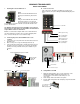
Photo identifying SATA ports on HPM
Power Switch
USB port
eSATA port
RAID config
rotary switch
RAID
setting
button
Power Connector
Use a ballpoint pen
tip to press the
RAID Setting Button
Power LED
Power Switch
(LED 1) HPM Health
(LED 3) USB Status
(LED 2) eSATA Status
(LED 1) HPM Health
(LED 3) USB Status
(LED 2) eSATA Status
HPM 1 (Top disk array)
HPM 2 (Snap-in racks)
LED pins
Pin 1
SATA
Port 2
SATA
Port 3
SATA
Port 1
SATA
Port 4
PM Health LED
eSATA LED
USB LED
USB Port
eSATA Port
Rotary Switch
USB 5-Pin Header
Pin 1
LED Pin Assignment
Rotary Switch