T E C H N O L O G I E S User Guide RAID Tower IV (RTIV35M2SU3) www.addonics.com v8.1.11 Technical Support If you need any assistance to get your unit functioning properly, please have your product information ready and contact Addonics Technical Support at: Hours: 8:30 am - 6:00 pm PST Phone: 408-453-6212 Email: http://www.addonics.
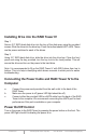
Installing Drive into the RAID Tower IV Step 1 Secure 3.5” SATA hard disk drive into the tray of the disk array using the provided screws. Slide the drive into the drive bay. Press the button labeled HD1~HD4. These are the power switches for each of the drives. Step 2 Using 3.5” SATA hard disk drive, slide the drive into the drive bay. Close the front panel and using the key provided, turn the key lock to the Lock position. This will secure the drive and turn on the power to the hard drive.
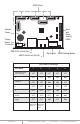
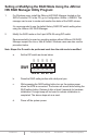
SATA Ports Error and Drive Activity LEDs Buzzer Alarm Floppy Power Connector USB 3.0/2.0 Host Port Dip Switch eSATA Host Port (Port 5) RAID Setting Button Dip Switch Settings Raid Mode 1 2 3 4 5 Individual Drive (Factory Default) OFF OFF OFF OFF OFF 0 OFF OFF ON ON ON 1 and 10 OFF OFF ON ON OFF 3 OFF OFF ON OFF OFF 5 OFF OFF OFF ON OFF Clone OFF OFF OFF ON ON Large OFF OFF ON OFF ON Enable ERR Buzzer Function www.addonics.
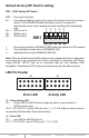
Default factory DIP Switch setting: SW1 – RAID Setting DIP Switch OFF OFF OFF OFF OFF BZS – Error buzzer function EZ – Automatic rebuilding to spare drive (one of the drives on the raid is set as a spare). If EZ is ENABLED anda drive failure occurs, the spare will automatically act as a drive replacement and rebuilding will automatically start. M2 – RAID mode 2 M1 – RAID mode 1 M0 – RAID mode 0 1 2 3 4 5 SW1 BZS EZ M2 M1 M0 1. 2. 3.
Setting or Modifying the RAID Mode Using the JMicron HW RAID Manager Utility Program: 1. For Windows users, install the JMicron HW RAID Manager located on the SATA Controller CD. In the CD, go to Configuration Utilities > JMB393. This manager can be use to create and monitor the status of the RAID volume. It is recommended to use the default factory RAID DIP switch setting when using the JMicron HW RAID Manager. 2.
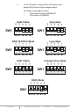
e. On the DIP switch, change (M0 to M2) setting to the desired RAID mode using the diagram below. SW1 1 ON 5 ON 4 OFF 3 Clone Mode OFF ON 2 OFF ON 1 ON SW1 RAID 0 Mode OFF OFF All settings on the diagram shows • Error buzzer function is ENABLED • EZ function is DISABLED.
RAID Setting Notes: RAID 1& RAID 10 Mode When 2 drives are SW1 1 2 3 4 5 BZS EZ M2 M1 M0 connected to the HPM-XA, and DIP switch is set to this setting, the 2 drives will be configured as a 2-drive RAID1 array. When 4 drives are connected to the HPM-XA, the 4 drives will be configured as a 4-drive RAID10 array. Clone Mode SW1 1 2 3 4 5 BZS EZ M2 M1 M0 Clone’s action is similar to RAID1. However, all of the hard drives will be mirrored.
Notes on Spare Drives using the Easy RAID Setting (EZ) When EZ function is ENABLED, the auto-rebuilding to spare drive is automatic. The degraded RAID group will start rebuilding automatically by using the existing spare drive. * Spare drive can be either plugged before RAID building or a new drive can be plug as the spare drive when RAID rebuild is required. A. B. Which port acts as a spare drive? The last drive will automatically become the spare drive.