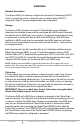
T E C H N O L O G I E S User Guide Secure NAS R5 (SN535E1G) www.addonics.com Firmware v87a Technical Support If you need any assistance to get your unit functioning properly, please have your product information ready and contact Addonics Technical Support at: Hours: 8:30 am - 6:00 pm PST Phone: 408-453-6212 Email: http://www.addonics.
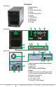
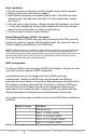
Overview SN535E1G 1.Reset Button 2. HDD 3. Cipher Key Socket 4. Power 5. Drive Activity LED 6. Power 7. NAS Status 8. RAID Error 9. Drive Error 10. Power 1 Front View 5 7 2 8 3 4 9 10 6 Back View 1 2 3 4 8 5 9 11 www.addonics.com 10 6 7 1. Extra Connector for Direct Attach Storage 2. Power LED 3. Status LED 4. DIP Switches for RAID Setting 5. Reset 6. RJ45 Connector for LAN Connecting 7. USB Connector for Additional USB Storage 8. 40x40mm Cooling Fan 9. Power Cord Socket 10.
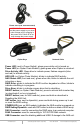
Power Cord (U.S. Version Shown) eSATA Cable WARNING: Please remember to set the power supply to your local outlet voltage prior to plugging in the power cord. Failure to do so may damage the power supply. Cipher Keys Network Cable Power LED (next to Power Switch): glows green while unit is turned on. Power LED (on Cipher Chain Module): glows green when Cipher is unlocked. Drive Activity LED: Glows blue to indicate power, flashes magenta (blue and red) to indicate activity.
Installation Network Connection The Secure NAS unit is factory configured for dynamic IP addressing (DHCP client). Connect the unit to a network (router or switch) where DHCP is supported. Static IP may be assigned later after initial setup. Storage The Secure NAS unit does not support FIS switching for port multipliers, otherefore the installed drives must be configured as a RAID array.
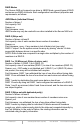
Drive Installation 1. Be sure all doors are unlocked, use the provided keys to unlock if needed. 2. Gently pull the lever on the door to release it. 3. Insert the drive as shown on the label inside the door: The SATA connector toward the rear, with label side to the right. The drive should slide in easily, don't force it. 4. Close the door on the drive bay. It should also give little resistance, don't force it. It can help to slightly tug the lever while snapping the door shut to make it easier.
RAID Modes The Secure NAS unit supports one drive in JBOD Mode, several types of RAID and some non-RAID drive sets. Each configuration has different properties and requirements, as follows: JBOD Mode (Individual Drives) Number of drives: 1 Unit capacity: N/A Spares: no Fault tolerance: none JBOD mode may only be used with one drive installed in the Secure NAS unit. RAID 0 (Stripe set) Number of drives: at least 2 Unit capacity: size of each member times number of members.
RAID 5 (Stripe set with striped parity) Number of drives: at least 3 Unit capacity: size of one member times number of members minus one. Spares: yes Fault tolerance: can withstand the loss of one drive without losing data. RAID 5 works by striping entire I/O blocks across all members of the set, with each member taking turns carrying parity data computed by the Port Multiplier. In the event of failure, the missing information can be calculated using the parity information.
Configuring the RAID Using Dipswitches Resetting the RAID NOTE: This procedure destroys all RAID data. It should not harm individual drives or their contents; however, creating backups of all data is strongly recommended before proceeding. Be sure the port multiplier is connected to an active host before proceeding. The port multiplier will not complete the process if it has no host connection. 1. Power down the unit and set the dip switch to the desired RAID Mode. 2.
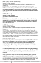
RAID Mode Switches M2, M1, M0 (SW1:3 – SW1-5) The RAID Mode switches define what type of RAID will be initialized when the unit is powered up while the RAID Mode button is held down, as follows: Dipswitch Position JBOD (Individual Drives) * FACTORY DEFAULT SETTING RAID 0 RAID 1 OR 10 RAID 3 RAID 5 CLONE LARGE 1 (BZS)1 2 (EZ) 3 (M2) 4 (M1) 5 (M0) OFF OFF2 OFF OFF OFF OFF OFF OFF OFF OFF OFF ON3 OFF OFF OFF OFF ON ON ON ON OFF OFF ON ON ON OFF ON ON OFF ON OFF OFF OFF ON ON NOTES: 1.
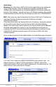
Initial Setup Windows: All of the Secure NAS unit's functions and features are configured using a Web Interface. Once the hardware is installed, access the Web Interface with a web browser on a computer attached to the same network by typing in “http://addnas” - this will work on most Windows systems. Be sure the computer accessing the NAS has the Workgroup name set to WORKGROUP.
Next, set up the Date and Time. Choose a city nearest you in the same Time Zone and be sure the Date and Time are correct. Finally, review and confirm the settings: After clicking on the Update settings button, Initial Setup is complete. Sharing Files Using the Secure NAS SMB (Windows Sharing) Connecting to the NAS for direct file access through Windows Explorer is very similar to sharing files between Windows systems.
On Mac systems, on the Finder's Go menu choose “Connect to Server...” then in the server address box type “smb://” followed by the Secure NAS unit's IP address. On Linux systems, use the “Connect to share...” dialog found on the Nautilus or “File Manager” menu bar, then select Windows Share for the type and complete the remaining fields for share name, username and password.
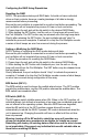
When first setting up, a prompt appears warning there is no password for the admin account. Click the space between the “DL” and “Input” buttons, then type the command “useradd admin” as shown, then add a password after a space. NOTE: The MLDonkey admin account is not the same account as the Secure NAS unit's web interface admin account. It is recommended that the password matches for simplicity, but not necessary.
Update Admin Username and Password Changes the web interface management login. Configure User Home Directory Drive Determines which drive on the system carries the HOME directory for users. The user's home folder is required for FTP transfers and as a network share for private files. If a home directory is already defined it will be shown. Choose a volume and click Save. If any files exist in a previous Home directory they will be moved to the new location.
Choosing Automatic will configure the Secure NAS unit as a DHCP client and the configuration wizard will skip to the end. Choosing Manual configuration will proceed to Step 2. Step 2 configures the Secure NAS unit's static IP address and subnet mask. To choose a working static IP address, make sure you meet these criteria: 1. The subnet mask must match the rest of the network exactly. 2. The IP address must match the router's IP address exactly where the subnet mask is "255." 3.
The next step is to configure network connections. The gateway is usually the internal IP address for the router the Secure NAS unit is connected to. DNS entries are usually the same as used by the router's external network configuration (determined by your ISP). Setting an NTP server will synchronize the Secure NAS unit to a time server, usually on the Internet. This can be a name or IP address.
View Drive Information Displays details of all connected drives. If network shares are configured for drives that have been disconnected, those drives will also appear in this list as unavailable. Device: The letter after “sd” is the drive's letter, in order of when the drive was first encountered by the NAS unit. The number at the end of the device label is the partition on the drive, in order of the drive's partition map. Vendor: The drive's manufacturer. Model: The drive's model number.
After clicking “Yes, I'm sure,” the format utility will create and prepare one partition on the selected drive, using all space on the disk. A page will load next confirming the format is in progress. This page updates once every minute. Once formatting is complete, the page will change to state it is done. Click any of the tabs above the message to perform other tasks.
The Sharing Tab User Management Shows current list of known users on the Secure NAS unit. To delete a user, click the “Delete” link next to that username, then confirm. To change a user's password, select the username just above “New Password,” then enter the new password into the “New Password” and “Confirm Password” fields and click “Change Password.” To create a new user account, click “New User,” then enter the new username and the initial password in the “New Password” and “Confirm Password” fields.
Step 1 is to define the name of the share. The share name will become the folder name on the drive. NOTE: The shared folder name will be written to disk using all capital letters. If an existing folder of the same name appears and is not all capital letters, the Secure NAS considers that not a match and writes the same folder name in all capital letters anyway. This can cause unpredictable results if the drive is subsequently connected to a computer.
Step 3 is to set the initial permissions for the new share. A permission setting for “Everyone” as well as each individual user is listed, with the default permission set to None for both SMB and FTP. Once you have reviewed the permissions for all users and made any desired changes, clicking on “Create Share Folder” will complete the Wizard. Rename A Shared Folder Changes the name of the directory as well as the share name for an existing shared folder.
Remove a Shared Folder Deletes a share from the Secure NAS unit. As a precaution this screen requires the word “yes” is typed in as confirmation. NOTE: Removing a shared folder also deletes the associated directory and all of its contents from the drive. It is however possible to delete the share without destroying any data: simply disconnect the drive physically from the Secure NAS unit before proceeding.