T E C H N O L O G I E S User Guide Storage Rack (SR46S4R5HM) www.addonics.com v8.1.11 Technical Support If you need any assistance to get your unit functioning properly, please have your product information ready and contact Addonics Technical Support at: Hours: 8:30 am - 6:00 pm PST Phone: 408-453-6212 Email: http://www.addonics.
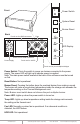
I O Front Power Switch POWER System Reset RESET Buzzer Reset Back Buzzer Punch out for USIB connectors Fans POWER LED Display FAN I O I O TEMP Punch out for USIB connectors Power Supply HDD Punch out for eSATA Punch out for port multipliers/bridges Power Switch: This is the switch to power on devices connected to the power supply. The power LED will light up to indicate power is supplied. Note: The main power switch located at the back of the enclosure must be turned on first.
I O I O Top Cover Screws O 3. I 2. Locate the 2 screws at the back of the storage rack Turn screws counterclockwise to loosen. Lift the top cover and pull towards the rear end of the rack. O 1. I How to Remove the Top Cover: 3. O I 2. Align the top cover with the edges of the rack. Lay it flat on the rack and slide it towards the front of the rack. Turn screws clockwise to tighten. O 1. I To Mount Back the Top Cover: Lift the chassis up. www.addonics.
How to Remove the 5 ¼” Drive Bay Front Panels: 1. 2. 3. Locate the 3 screws for each front panel. Turn screws counterclockwise to loosen. Pull the front panel forward, away from the drive cage. 3 screws for each panel Thermal Management Card on the RAID Rack Fan Connectors Overheat Buzzer Floppy Power Connector Ambient Detect Terminal Temp. Setting (40°C, 50°C, 60°C) Fan, Temperature and Power LED Connectors Fan Detect Selection Features Fan1 to Fan8 could be set either “ENABLE” or “DISABLE”.
4x1 Hardware Port Multiplier (AD4SR5HPMU-E) RAID config rotary switch USB port connection to any USB controller RAID setting button eSATA Port PM Health LED eSATA LED USB LED SATA Port 4 SATA Port 1 Pin 1 SATA Port 2 USB 5-Pin Header Pin 1 LED pins SATA Port 3 Rotary Switch USB 5-Pin Header Pin Assignment LED Pin Assignment LED Status Drive Activity LED: Always ON. The LED blinks when there is drive activity. PM Health: Always OFF when RAID volume is working correctly.
Setting RAID on the HPM 1. Attach the SATA hard drives (up to 4) to the SATA ports on the Hardware Port Multiplier (HPM) using SATA cables. It is recommended to connect drives to the SATA ports 1 to 4 successively. 2. Set the Rotary switch to the RAID mode required. 3. Push the RAID setting button with a ballpoint pen tip while the HPM is turned off. Use a ballpoint pen tip to press the RAID Setting Button 4.
Installing the 4th Disk Array on the Storage Rack a. Remove the back panel of the storage rack by loosening the 4 screws indicated below. I O I O Screws b. Secure the bottom bracket of the storage rack to the disk array using screws. c. Secure the top bracket of the storage rack to the disk array using screws. R d. Slide the disk array into the storage rack. www.addonics.com Technical Support (M-F 8:30am - 6:00pm PST) Phone: 408-453-6212 Email: www.addonics.
Screws Secure the Disk array by screwing the top and bottom brackets to the frame of the storage rack. I O R I O e. Screws Installing Storage Devices on the Storage Rack A. 3.5” hard drive 1. Attach the 3.5” to 5.25” mounting brackets onto both sides of the 3.5” SATA or IDE hard drive using the included screws. 2. Attach the ventilation front panel and base onto one side of the mounting bracket using the black screws included with the Storage Rack. www.addonics.
B. 5.25” Storage devices 1. Separate the ventilation front panel and the metal base by removing the two flat-head screws. 2. Attach the metal base onto the optical drive or other 5.25” storage device using the flat head screws from the ventilation front panel. Optical Drive Addonics Drive Cradle www.addonics.com Technical Support (M-F 8:30am - 6:00pm PST) Phone: 408-453-6212 Email: www.addonics.
C. 3.5” Mobile Rack 1. Separate the ventilation front panel and the metal base by removing the two flat-head screws. 2. Attach the 3.5” drive cradle onto the 3.5” to 5.25” drive bay mounting bracket at the six aligned screw hole locations. 3. Attach the metal base onto the optical drive or other 5.25” storage device using the flat head screws from the ventilation front panel. With the storage device connected, slide the metal base back into the drive cage.
At the bottom of the drive cage, locate the metal base corresponding to the storage device inserted in the previous step and secure it onto the drive cage. O I O I When you finished, install the drive cage now populated with the devices back into the Storage Rack. www.addonics.com Technical Support (M-F 8:30am - 6:00pm PST) Phone: 408-453-6212 Email: www.addonics.
Installing Additional Bridge Boards on Mounting Poles Inside the Storage Rack Separate PM or HPM from bracket by unscrewing 4 screws on the PCB. Install the PM or HPM onto the desired mounting pole. Installing Bridge Boards onto Back Panel I O I O Remove punch outs from the rear panel of the Storage Rack. Using the included screws, attach bridge board onto the desired back panel mounting location.
Power Supply O I This power supply provides 500W of power. Before turning on the main switch located on the front panel of the storage rack, turn on the power switch of the power supply. Power Switch Fan Storage Rack DA with Port Multiplier Using Multilane Connection Note: The Port Multiplier will only work with Port Multiplier aware multilane host controllers. It is compatible with multilane host controllers using the Silicon Image Chip SiI3124 & SiI3132.
CONTACT US www.addonics.com Phone: Fax: Email: 408-573-8580 408-573-8588 http://www.addonics.