About Adeept Adeept is a technical service team of open source software and hardware. Dedicated to applying the Internet and the latest industrial technology in open source area, we strive to provide best hardware support and software service for general makers and electronic enthusiasts around the world. We aim to create infinite possibilities with sharing. No matter what field you are in, we can lead you into the electronic world and bring your ideas into reality. Technical Support: support@adeept.
Contents Contents...............................................................................................................................................1 Components List................................................................................................................................. 1 Introduction of Robotic Arm...............................................................................................................6 Introduction of Adeept Arm Drive Board.........................
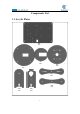
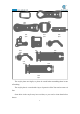
Components List 1.
A10 1pcs A09 1pcs A11 1pcs A14 2pcs A13 1pcs A12 1pcs A15 1pcs A16 1pcs A17 1pcs A18 1pcs A19 1pcs The acrylic plates are fragile, so please be careful when assembling them in case of breaking. The acrylic plate is covered with a layer of protective film. You need to remove it first. Some holes in the acrylic may have residues, so you need to clean them before the use.
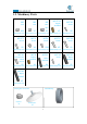
1.2. Machinery Parts M2.5*11 M2 M3 M3 Nut Nut Lock Nut X11 X7 X3 X2 X9 M2.5*7 M3*5 M3*8 M3*12 Screw Screw M3*18 Copper Standoff M2*10 Screw www.adeept.com www.adeept.com www.adeept.com www.adeept.com www.adeept.com Screw Screw Screw X5 X4 X18 X5 X1 M3*10 M3*8 M3*15 M2*18 M3*30 www.adeept.com www.adeept.com www.adeept.com www.adeept.com www.adeept.com Countersunk Head Screw X2 Copper Standoff Nylon Standoff X1 X4 Screw X2 Nylon Standoff X5 www.adeept.com www.
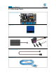
1.3.
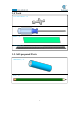
1.4 Tools Cross Socket Wrench X1 Large Cross-head Screwdriver Ribbon X1 X1 Winding Pipe X1 1.5.
Introduction of Robotic Arm Nowadays, under the progress of science and technology, the biggest difference between a robotic arm and a human arm lies in flexibility and strength. That is, the biggest advantage of the robotic arm is that normally it can repeat the same motion without feeling tired. Today Adeept recommends a robotic learning kit to learn how to assemble a robotic arm and learn how to write the code to control the robotic arm to perform the specific motions.
The following figure shows that we control the robotic arm to write and draw through the mouse with serial communication.
We have added the learning and memory function to the robotic arm. We let the robotic arm to record the manually controlled mechanical movements we made, and the robotic arm can learn repeatedly, such as repeat moving the object, repeat drawing the same graphic, repeat keyboard input and repeat turning book pages.
Introduction of Adeept Arm Drive Board The Adeept Arm Drive Board development board is the main component of the robotic arm. Similar to the Arduino UNO development board, it is also an easy-to-use open source electronic prototyping platform, including the hardware part and the software part (Arduino IDE). The Adeept Arm Drive Board development board is mainly composed of a microcontroller (MCU), a universal input/output interface, etc. You can understand it as a microcomputer motherboard.
It is the pin interface for external power supply. Use 6-24V external power supply to power the Adeept SmartHub development board. 【4】RESET: Restarting the Adeept SmartHub development board. 【5】Switch: When using Vin (6-24V) as an external power supply, Switch can control the OFF and ON of the Adeept SmartHub development board.
Lesson 0 Building the Arduino Development Environment 1. Arduino development language Arduino uses C/C++ to write programs, so before learning Arduino, you need to master the C/C++ language. Although C++ is compatible with the C language, these are two different languages. C is a process-oriented programming language, and C++ is an object-oriented programming language. The early Arduino core library was written in C language. Later, object-oriented ideas were introduced.
and loop() are used instead. 3. The construction of the Arduino development environment The IDE of the Arduino development environment can be downloaded from the official website. The download address of the Arduino IDE is: https://store.arduino.cc/usa/ (1) Install Arduino IDE under Windows We will teach you how to download and install: 1.Open Google Chrome and enter the URL in the address bar: https://store.arduino.
3. We click the installation package of Windows ZIP file for non admin install.After the interface jumps, we select JUST DOWNLOAD.And then start the download. The download status will be displayed in the lower left of Google Chrome.Then we wait for the download to complete.
4.After the download is complete, open the folder.There are downloaded compressed installation files: arduino-1.8.12-windows.zip 5. Double-click to open the file and unzip it.
6. The file arduino-1.8.12 appears after decompression.As shown follows; 7. Open the arduino-1.8.12 folder and double-click arduino.exe to open the software. 8. The interface will show as follows after the Arduino software is opened, indicating that our software has been downloaded and installed successfully.
4.
(1)Menu bar Menu bar contains File, Edit, Sketch, Tools and Help. (1) "File" can operate new file, open file, save file, close file, save, etc. For the Examples, you can check the official sample program. (2) "Edit" has the functions for the program code of editing, copying and pasting, commenting, indenting,searching, etc.
written project. The Include Library can load the library. After selecting the library file in the list, the relevant header files are automatically added in the code editing area.
(4) Board and Port are often used in "Tools". Board can choose different development boards. Our course uses Arduino Uno development board, so we need to choose Arduino Uno. The list contains many Arduino development board models.We choose the corresponding ones according to the model.
Port can set the port used by Arduino IDE to download the program, that is, the port number of the development board connected to the computer. The port display of each computer is different. When we use the Arduino Uno to connect to the computer, it displays the COM3 port number.
Button bar includes functions of Verifying,Uploading,Building New,Opening and Saving. (1)Verify : Checking and compilation. This button is used to check the correctness of your "syntax" or code. If your code has any syntax errors or undefined variables, an error message will appear at the bottom of the IDE screen. At the same time, the line of error code will be marked with a red background color for easy modification. But if it is correct, you will see the message that the compilation is complete.
5.Connecting the Adeept Arm Drive Board and the computer (1)Connecting the Adeept Arm Drive Board and the computer You need to use USB Cable to connect the Adeept Arm Drive Board to the computer.As shown below: (2) Select the Arduino Uno development board in Tools Open Arduino IDE under Tools—>Board.Select Arduino UNO in the list. (3)Install CH341SER driver 1.
2. You need to find the user folder provided by Adeept: AdeeptRoboticArmforArduinoV3_5, find the 01 Software Package folder, and open the Adeept driver folder. If you are using a Windows system, you can directly double-click to open CH341SER_Windows.EXE, install corresponding driver according to the computer operating system. 3. Click INSTALL.Wait for the installation to succeed.And click OK.
4.Now you will find the Arduino serial port is accessible (different computer configuration has different serial port).
board has been successfully connected to the computer. You will need to pay attention to this connection step in the following course. 6.The solution for situation that Arduino IDE cannot be opened When opening the Arduino IDE, you will suddenly encounter a situation that it cannot be opened.
You need to find the Arduino15 folder in the \Users\ASUS\AppData\Local\Arduino15 directory of the C drive.As shown below: You need to delete the package_index.json file, and then reopen the Arduino IDE. 7、Download Processing Processing is a revolutionary and forward-looking new computer language. Its concept is to introduce programming languages in the environment of electronic art and introduce the concept of electronic art to programmers.
2. Click Download Processing, as shown below: 3.The operating system we choose to use here is windows 64-bit, select "Windows 64-bit".
4.When finish downloading, you will get a compressed file "processing-3.5.4-windows64.zip". 5.After extracting this file, you can get the following file, just click to run processing, it can be run directly without installation. 6.
7.Let's write a simple code that implements the following functions "Change the variable to create a moving line. When the line moves out of the window edge, the variable becomes 0 and the line goes back to the bottom of the screen 8.Click “Run”.
9.Running effect is as follow.
8. Configuring the "libraries" folder of the Arduino IDE Before using Adeept Robotic Arm, you need to configure the "libraries" folder under the downloaded Arduino IDE directory.
You need to copy all files to the "libraries" under the Arduino IDE installation directory, as shown in the figure below: Paste the three folders in "libraries".
Lesson 1 How to Read the Data of the Potentiometer In this lesson, we will learn how to read the data of the potentiometer and convert the data into an angle. 1.1 Components used in this course Components Quantity Adeept Arm Drive Board 1 Micro USB Cable 1 Picture 1.2 Introduction of Potentiometer (1) Potentiometer The potentiometer is a resistance element with three terminals and the resistance value can be adjusted according to a certain change law, which is equivalent to a variable resistor.
fixed contact. Potentiometer can be used to adjust the voltage and current. Our course uses a rotary potentiometer. Its structure is as shown in the figure below. By rotating the knob, the position of pin 2 is changed, thereby changing the resistance value from pin 2 to both ends. In the experiment. Connect pin 1 and pin 3 to the GND and 5V of the development board respectively. And then read the voltage divided by the pin 2 of the potentiometer through the analog input pin A0.
1.4 Reading the value of the potentiometer and converting it into an angle 1.4.1Compile and run the code program of this course 1.Open the Arduino IDE software, as shown below: 2. In the Tools toolbar, find Board and select Arduino Uno, as shown below: 3.
4.Click Open in the File drop-down menu: 5.Find the folder AdeeptRoboticArmforArduinoV3_5 that we provide to the user. Open the folder 02 Course Code in it. Enter the Lesson 1 potentiometer directory. Select potentiometer.ino. This file is the code program we need in this course. Then click Open.
6.After opening, click to upload the code program to the Arduino UNO. If there is no error warning in the console below, it means that the Upload is successful. 7.
Then open the serial monitor, you need to modify the displayed bit rate and the bit rate set in the code to 115200, so that the display will not appear garbled. You can observe the data changes corresponding to each button by rotating the buttons of A0, A1, A2, A3, and A6. When the buttons of A0, A1, A2, and A3 are rotated, the data change range is from 0 to 180. The data becomes smaller when rotating clockwise, and the data becomes larger when rotating counterclockwise.
1.4.2 Learning the code program of this lesson Initialize potentiometers A0, A1, A2, A3, A6. Initialize the serial monitor. Convert the value of 1023 to 180 proportionally, and then print out the converted data to the serial monitor.
Lesson 2 Controlling the Servo In this lesson, we will learn how to control the Servo. 2.1Components used in this course Components Quantity Adeept Arm Drive Board 1 Micro USB Cable 1 Servo 1 Picture 2.2 The introduction of the Servo 2.2.1 Servo Servo motor refers to the engine that controls mechanical component operation in the servo system. It is a kind of auxiliary motor indirect transmission device. The servo motor is a gear motor that can rotate only 180 degrees.
2.2.2 The working principle of the Servo The servo mechanism is an automatic control system that enables the object's position, orientation, state and other output controlled quantities to follow arbitrary changes in the input target (or given value). The servo mainly depends on Pulsefor location. Basically, it can be understood that the servo motor receives an impulse and rotates the angle corresponding to the impulse to realize displacement.
2.2.3 The principle of write () function In the program, we use the write() function to control the rotation of the servo. For standard servos, the write() function will rotate the servo axis to the corresponding angular position.
2.3Wiring diagram (Circuit diagram) Connect Servo to the servo port on the Adeept Arm Drive Board, as shown below: 2.4 How to control Servo 2.4.
1.Open the Arduino IDE software, as shown below: 2. In the Tools toolbar, find Board and select Arduino Uno, as shown below: 3.In the Tools toolbar, find “Port” and Select the port number of The Adeept Arm Drive Board , as shown below: 4.
5.Find the folder AdeeptRoboticArmforArduinoV3_5 that we provide to the user. Open the folder 02 Course Code in it. Enter the Lesson 2 servo directory. Select servo.ino. This file is the code program we need in this course. Then click Open. 6.After opening, click to upload the code program to the Arduino UNO. If there is no error warning in the console below, it means that the Upload is successful.
7. After successfully running the program, you will observe the movement of the servo. 2.4.2 Learning the code program of this lesson Create servo object to control a servo. In the setup() function, attach the servo on pin 9 to servo object; back to 0 degrees; wait for a second. In the loop() function, respectively control Servo to turn to different angles.
Lesson 3 Displaying Text on the OLED Screen In this lesson, we will learn how to display text on the OLED screen. 3.1 Components used in this course Components Quantity Adeept Arm Drive Board 1 Micro USB Cable 1 OLED screen 1 Picture 3.2 Introduction of OLED Screen OLED (Organic Light-Emitting Diode), also known as organic electric laser display, organic light emitting semiconductor (Organic Electroluminesence Display, OLED).
3.3 Wiring diagram (Circuit diagram) You need to connect it to the OLED interface on the Adeept Arm Drive Board.As shown below: 3.4 How to display text on the OLED screen 3.4.
1.Open the Arduino IDE software, as shown below: 2. In the Tools toolbar, find Board and select Arduino Uno, as shown below: 3.In the Tools toolbar, find “Port” and Select the port number of The Adeept Arm Drive Board , as shown below: 4.
5.Find the folder AdeeptRoboticArmforArduinoV3_5 that we provide to the user. Open the folder 02 Course Code in it. Enter the Lesson 3 OLED directory. Select OLED.ino. This file is the code program we need in this course. Then click Open. 6.After opening, click to upload the code program to the Arduino UNO. If there is no error warning in the console below, it means that the Upload is successful. 7. After successfully running the program, you will observe that text will be displayed on the OLED screen.
In the loop() function, set the display font size with setTextSize(1); setCursor(30,30) sets the position of the text displayed on the OLED screen, and print("TEST") prints out the text information that needs to be displayed.
Lesson 4 Saving Data with EEPROM In this lesson, we will learn how to save data with EEPROM. 4.1 Components used in this course Components Quantity Adeept Arm Drive Board 1 Micro USB Cable 1 Picture 4.2 About EEPROM EEPROM (Electrically Erasable Programmable Read Only Memory) refers to electrically erasable programmable read only memory. It is a memory chip that does not lose data after power failure. EEPROM can erase existing information on a computer or special equipment and reprogram it.
4.4 How to use EEPROM to save data 4.4.1 Compile and run the code program of this course 1.Open the Arduino IDE software, as shown below: 2. In the Tools toolbar, find Board and select Arduino Uno, as shown below: 3.
4.Click Open in the File drop-down menu: 5.Find the folder AdeeptRoboticArmforArduinoV3_5 that we provide to the user. Open the folder 02 Course Code in it. Enter the Lesson 4 EEPROM directory. Select EEPROM.ino. This file is the code program we need in this course. Then click Open.
6.After opening, click to upload the code program to the Arduino UNO. If there is no error warning in the console below, it means that the Upload is successful. 7.
You will see the returned information in the serial monitor: Read Succes, indicating that the data has been saved successfully. 4.4.
EEPROM. Below we will introduce how the main code program is implemented. In the setup() function, first initialize the serial monitor, EEPROM.read(5) reads the data, and judges by if, if the read data is 2, then it is saved successfully.
Lesson 5 Servo 90 degree adjustment Before assembling the robotic arm, we first need to adjust the 5 servos of the robotic arm by 90 degrees. 5.1 Components used in this course Components Quantity Adeept Arm Drive Board 1 Micro USB Cable 1 Servo 5 Picture 5.
5.3 Upload the Servo90.ino 1.Open the Arduino IDE software, as shown below: 2.
3.In the Tools toolbar, find “Port” and Select the port number of The Adeept Arm Drive Board , as shown below: 4.Click Open in the File drop-down menu: 5.Find the folder AdeeptRoboticArmforArduinoV3_5 that we provide to the user. Open the folder 02 Course Code in it. Enter the Lesson 5 Servo90 directory. Select Servo90.ino. This file is the code program we need in this course. Then click Open.
6.After opening, click to upload the code program to the Arduino UNO. If there is no error warning in the console below, it means that the Upload is successful. 7.After successfully running the program, You will see that all the servos will turn to 90 degrees. 【Note】: For the adjusted servos, it is forbidden to rotate them when assembling the robotic arm, otherwise it will cause errors in the assembly of the robotic arm. 8.
Lesson 6 How to Assemble the Robotic Arm 6.1 Pedestal Assembly 1.Fix four Sucking Discs on the four corners of A01.
2.Fix OLED to drive M2*18 Screw M2.
3.Fix 18650x2 Battery Holder to A01. Assemble the following components M3*10 Countersunk Head Screw x2 The wires of 18650x2 Battery Holder are near inside.
4.Fix four M3*6 Copper Standoffs to A01.
5.Fix Adeept UNO R3 Board to M3*6 Copper Standoff. Assemble the following components M3*5 Screw x4 Adeept UNO R3 Board x1 Effect diagram after assembling 6. Fix four M3*30 Nylon Standoffs to A01.
Assemble the following components M3*30 Nylon Standoff x4 M3*8 Screw x4 Effect diagram after assembling 67
Connect the 18650x2 Battery Holder to Adeept Arm Drive Board. Switch The anode (red wire) of the 18650x2 Battery Holder connects to the VCC interface. The negative (black wire) is connects to the GND interface. And the switch is turned off. Once the circuit is connected, load your 18650 battery into 18650x2 Battery Holder and turn on the switch on the Adeept Arm Drive Board. At this point, the servo will automatically rotate to the initial state, then turn off the power and remove each servo.
6.1.2 Install and Remove Batterries Take out 2 ribbons and 2 batteries. Roll one end of the ribbon to let through a battery and fix. Insert the batteries into the rings-ribbon closer to the anode. Install the batteries into the holder based on the pole. To remove the batteries, just pull the ribbon and take them out.
6.1.3 Turnplate and Rocker Arm Assembly Servo debugging ( If you have already adjusted the steering gear to 90 degrees according to Lesson 5, then you don’t need to adjust it anymore, please proceed to the next part) Connect five servos to the Adeept Arm Drive Board. For convenience to read, only one end of the servo power cable is shown here. ` Connect No. 1-5 servo, and increase from No. 1-5 in the direction close to the oled screen.
SERVO of number 5 3 4 2 1 71
2. Fix a debugged servo to A02 and A03. Assemble the following components M2*10 Screw A03 A02 For convenience to read, A02 is displayed in green, and the color of all acrylic sheets is subject to the actual product.
3. Then fix A02 to M3*30 Nylon Standoff.
4.Assemble 51108 Bearing. Assemble the following components Put 51108 Bearing on A03 as shown in the figure.
5.Take a rocker arm as in the illustration and connect it to A04. Assemble the following components Rocker arm A04 Effect diagram after assembling x1 Note that the center of the rocker arm is aligned with the center of the A04. x1 Screw the self-tapping screw just into the rocker arm. Self-tapping screw packaged with x2 servo 6. Take two rocker arm as in the illustration and connect them to A07.
8. Then fix one end of A07 to the servo on A06. First install the rocker arm on the A07 into the servo. When installing, the mounting hole of the rocker arm should be aligned with the round hole on the A07. Install it at the angle shown below. Assemble the following components M2.5*7 Screw A07 x1 Effect diagram after assembling Please note that when installing the servo arm, please connect the servo to the robot drive Hat.
9. Fix a debugged servo to A10. Assemble the following components M2*10 Screw x2 A10 Effect diagram after assembling x1 A09 x1 Servo x1 M2 Nut x2 10. Then fix the other end of the A07 to the servo on the A10. First install the rocker arm on the A07 into the servo. When installing, the mounting hole of the rocker arm should be aligned with the round hole on the A07. Install it at the angle shown below. Assemble the following components M2.
11. Then fix A06 to A04.
12.Connect A05 with A08 and A11. Assemble the following components M3 Lock Nut x2 A08 A11 x1 x1 A05 M3*12 Screw x1 x2 Do not tighten between M3 Lock Nut and M3*12 Screw. Allow rotation between A05 and A08, also A08 and A11.
13. Fix A05 to A04.
14. Fix the rocker arm under A04 with the servo on A02. The angle when the rocker arm is installed into the servo is as shown below.
Effect diagram after assembling Then fix the rocker arm to the servo with the fixing screw packaged with servo.
Effect diagram after assembling 83
6.2 Play 1 Fix A18 between A10 and A11. Assemble the following components M3 Nut x2 M3*8 Screw A18 x1 x2 Choose A18 or A19 according to the actual size of the pen.
Fix the pen with A18. Assemble the following components Pen M3 Nut x1 x1 M3*12 Screw x1 Effect diagram after assembling The tip of the pen should be 60 mm away from A18.
6.3 Play 2 1. Fix one M3*8 Copper Standoff to A15. Assemble the following components Effect diagram after assembling M3*8 Copper Standoff A15 Install it in strict accordance with the position shown in the figure. Do not mount the M3*8 Copper Standoff on the other side of the A15. M3*18 Screw x1 2. Fix a debugged servo to A15.
3. Fix one rocker arm of the servo to A17. Assemble the following components Rocker arm A17 Effect diagram after assembling x1 x1 Self-tapping screw packaged with servo x1 4. Assemble A16 and A17. Install A16 and A17 as shown below. A16 A17 Assemble the following components M3 Lock Nut x1 A16 M2.5*7 Screw Effect diagram after assembling x1 x1 Do not tighten the M3 Lock Nut to ensure that the A16 can rotate.
5.Fix a debugged servo to A12. Assemble the following components M2*10 Screw A12 Effect diagram after assembling x2 x1 Servo x1 M2 Nut x2 6. Fix a rocker arm to A13.
7. Fix the rocker arm on the A13 to the servo on the A12. Install as shown below.
8. Fix one A14 with two M3*40 Nylon Standoffs. Effect diagram after assembling Assemble the following components M3*8 Screw A14 x2 x1 M3*40 Nylon Standoff x2 9. Complete assembly of the clamp section.
Install the clamp section on the robotic arm. Assemble the following components M3*8 Screw M3*30 Nylon Standoff x1 Effect diagram after assembling Servo5 Servo4 Servo3 Servo2 Servo1 Number each servo to prepare for the circuit connection.
66.
6.4 Circuit Connection Connection of each devices for the robotic arm: Insert the servo numbered in the last step into the port here correspondently. The color of the three power cables of the servo corresponds to the port color (as shown on the left).
6.5 Combinations of the robotic arm Assemble method (except the front part of the robotic arm). 6.6 Adjustment of the robot arm Before starting to exert the function, we need to test whether there are problems with the assembly of the robotic arm.
【If your robot arm is assembled and turned on, it is not what it looks like in the picture above, then how do you adjust it?】 1.First, you need to re-download the code used in lesson 5: Servo90.ino. Observe if the robot arm is close to the one in the picture above. 2.
96
Lesson 7 GUI application control mode In this lesson, you will learn how to control the movement of the robotic arm with the GUI application. 7.1 Downloading and installing Python (1) Log in to the official website by browser: https://www.python.org/downloads/ (2) Click the "Download Python 3.8.
(4) Select the "Add Python 3.8 to PATH" option: (5) Then click "Install Now" to install. (6) Wait for the Python installation to complete and click "Close" to close.
7.2 Installing pySerial pySerial encapsulates the serial communication module,supporting Linux, Windows, BSD (may support all operating systems that support POSIX), Jython (Java) and IconPython (.NET and Mono). The pyserial module encapsulates access to the serial port.The port number starts from 0 by default.There is no need to know the port name in the program. APIs like file reading and writing, read and write (readline, etc.
Before downloading and installing, you need to connect the Adeept Arm Drive Board development board to your computer. (1) Press Win+R shortcut key to open CMD under Windows 10: (2) Click "OK": (3) Enter the command in the window: pip install pyserial Press the Enter and wait for the installation to complete.
7.3 Opening the GUI interface (1) Enter the folder "AdeeptRoboticArmforArduinoV3_5" → "01 Software Package" → "block_py" provided by Adeept for users, and find this file: "block_py.ino". (2) Then right-click the file: "block_py.ino". Select "Open with" → "Choose another app". (3) Click "More apps", and then click "OK".
(4) Use the mouse to slide down, click "Look for annother app on this PC", and then click"OK". (5) Find the Arduino software on the Desktop or where you installed the Arduino software, select it, and finally click "Open".
(6) At this time, the Arduino software opens the file "block_py.ino". (7) First select the Arduino development board as UNO version with Tools.
(8) Then continue to use Tools to select the port “Port” of the Adeept Arm Drive Board connected to the computer. (9) Click the Upload button to download the code program to the Arduino development board.
(10) Find the folder AdeeptRoboticArmforArduinoV3_5"→"01 Software Package"→"websocket", find this file: "servosGUI.py". (11) Double-click to open this file: servosGUI.
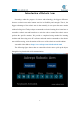
(12) After the GUI is opened, as shown in the figure below, you need to fill in the Port in the Arduino IDE in the Port input field. For example, the Port connected to the Arduino IDE is COM5, then you enter COM5, and then click Connect. After successfully connecting, there will be a prompt message in the upper left corner: "COM5: Succes". 7.
Note that the arm is still connected to the computer with the USB cable. 1. In the opened GUI interface, the left area is to control the movement of the servo D1~D5, and the right area is the structure diagram of the servo of the robotic arm. 2. When you need to control the robotic arm, you can slide the slider corresponding to the servo in the left area to control the movement of the robotic arm. When a certain position is slipped, a data will be displayed on the slider, this data represents the angle.
108
Lesson 8 GwBlock graphical control mode We creatively provide users with Arduino graphical programming tools-GwBlock. Using graphical program instruction blocks to achieve control of Arduino with the Web page. Compared with the traditional pure character interface code programming platform, graphical programming is more conducive to learners who have not mastered C/C++. If you have studied Scratch, then you will be able to easily master the graphical programming of Arduino.
(3) Open the downloaded file, double-click to open it to install: (4) Select the "Add Python 3.8 to PATH" option: (5) Then click "Install Now" to install.
(6) Wait for the Python installation to complete and click "Close" to close. 8.
pySerial encapsulates the serial communication module,supporting Linux, Windows, BSD (may support all operating systems that support POSIX), Jython (Java) and IconPython (.NET and Mono). The pyserial module encapsulates access to the serial port.The port number starts from 0 by default.There is no need to know the port name in the program. APIs like file reading and writing, read and write (readline, etc. are also supported), support binary transmission, no null elimination, no cr-lf conversion.
(3)Enter the command in the window: pip install pyserial Press the Enter and wait for the installation to complete. (4) Open the folder "AdeeptRoboticArmforArduinoV3_5" provided by Adeept to the user → “01 Software Package”→"block_py" and find this file: "block_py.ino". (5) Then right-click the file: "block_py.ino". Select "Open with" → "Choose another app".
(6) Click "More apps", then click "OK". (7) Slide the mouse down, click "Look for annother app on this PC", and then click "OK".
(8) Find the Arduino software on Desktop or the place where you installed the Arduino software, select it and click "Open". (9) Then the Arduino software opens the file "block_py.ino".
(10) First select the Arduino development board as UNO version with Tools. (11) Then continue to select the "Port" of the Adeept Arm Drive Board connected to the computer with Tools.
(12) Click the Upload button to download the code program to the Arduino development board. (13) We re-use the Arduino software to open the "block_py.ino" file, and then click the Upload button again to download the code program to the Adeept Arm Drive Board development board.
(14) Find the folder AdeeptRoboticArmforArduinoV3_5"→"01 Software Package"→"websocket", find this file: "GUI info v1.0.py". (15) Double-click to open this file: GUI info v1.0.
(16) After opening the file, the following interface will appear. We need to record this IP address, which will be used later: 192.168.3.69 (17) In the input box, enter the port we set in step (11).Everyone's port is different.The port of my Adeept Arm Drive Board development board is: COM4. After entering, click the Connect button. (18)Enter the URL of the GwBlock graphical editor in the browser: http://www.adeept.
(19) Click the "Connecting device" button in the upper right corner. In the pop-up box, enter the IP address we recorded in step (16), as shown below, and then click the Connecting button. (20) After the connection is successful, a green "connected" will appear in the lower left corner of the interface, indicating that the connection with the Adeept Arm Drive Board is successful.
8.3 The method of reconnecting the GwBlock graphical editor In the following cases, you need to reconnect to the GwBlock graphical editor: [1] When you close the GwBlock editor. [2] When you close the Adeept Arduino Robot window. [3] When you restart the computer. [4] When you log in to the GwBlock website again. [5] When you close the Arduino IDE. (1) Before doing the experiment, you must first connect the Arduino development board to the computer.
(3)Open this folder: block_py again, and find a block_py.ino file inside, as shown below: (4) Double-click to open this block_py.ino file (use Arduino to open!), as shown below: (5) Select COM4 as the port of Adeept Arm Drive Board in Tools in the toolbar of Arduino IDE, and click the icon in the upper left corner to download the program to the Arduino development board.
as follows: (6)Next, open the folder we provide to the user: AdeeptRoboticArmforArduinoV3_5 Then open 01 Software Package.As shown below: (7) Open the websocket folder.There is a file inside: GUI info v1.0.py. (8) Double-click to open the GUI info v1.0.py file, and the following picture will appear after opening: (9) After opening the file, the following interface will appear. We need to record this IP address, which will be used later: 192.168.3.
(10) Enter the Arduino software download program in the input box of Adeept Arduino Robot.The connected port number: COM4. Click the Connect button.As shown below: (11)Enter the URL of the GwBlock graphical editor in the browser: http://www.adeept.com/gwblock/?hd_mo=uno_r3.
(12)Click the "Connecting device" button in the upper right corner. It will show as below: (13) In the pop-up box, enter the IP address in step (9): 192.168.3.69. And then click the Connecting button, as shown below: (14) After a successful connection, as shown below, a green connected prompt will appear in the lower left corner. It means that we have successfully connected to the GwBlock graphical editor, with which we can realize the graphical programming of Arduino.
8.4 Get to know about Arduino's graphical editor GwBlock The functions of the buttons on the main interface of the GwBlock editor will be described in detail below according to the function numbers in the picture. As shown below: 【1】 Blocks: Click this button to switch to the programming mode of the graphical code block.
【2】Python: Click this button to display the edited graphical code block in the form of Python code. 【 3 】 Connecting device: Click this button to connect to the Arduino development board, which requires you to enter the IP address. 【4】 (1) : is the cancel button.Click it to return to the state of the previous operation (cancel this operation). (2) is the forward button.Click it to advance to the state of the next operation. (3) is the button to run the program.
button to the right of English. Currently, we only support English and Simplified Chinese. 【 6 】 is the icon of the Arduino UNO development board, indicating that it is currently in the Arduino programming mode. 【7】 is the camera button, which is gray in the initial off state: the camera will turn red: When you click it, ,indicating that the camera is on. At this time, a screen window will appear in the editing area on the right. As shown below: 【8】is the code instruction module toolbar.
【9】is the editing area (code area or work area), where we edit the code instruction block. Each code instruction block must be placed below . 【10】 is the connection status of the device.There are two states: (1) The following is displayed when the device is not connected: (2) After the device is successfully connected, the display is as follows: 【11】is a code trash, you can drag and drop the code instruction block to delete it. 8.
2. Then click Import project file to import the external project file. After opening it, a blank page will appear. You need to make a modification in the lower right corner and select All Files, as shown below: 3. Then the folder will be displayed. As shown below: 4.
5. Open the Lesson 8 block folder and select the "main.gwblock" file. This file is our graphical code program for this lesson. Click "Open" in the lower right corner, as shown below: 6. Click OK, as shown below: 7.
program, you can control the movement of the robotic arm by rotating the potentiometer button on the Adeept Arm Drive Board.
In the GwBlock graphical editor, all code programs are executed from Initialize the servo. Read the data of the potentiometer button. Convert the read potentiometer analog data. Control the movement of each servo respectively. 133 .
134
Lesson 9 Potentiometer control mode In this lesson, we will introduce how to control the movement of the arm through the potentiometers on the Adeept Arm Drive Board. 9.1 Upload the Potentiometer_control.ino 1.Open the Arduino IDE software, as shown below: 2. In the Tools toolbar, find Board and select Arduino Uno, as shown below: 3.
4.Click Open in the File drop-down menu: 5.Find the folder AdeeptRoboticArmforArduinoV3_5 that we provide to the user. Open the folder 02 Course Code in it. Enter the Lesson 9 Potentiometer_control directory. Select Potentiometer_control.ino. This file is the code program we need in this course. Then click Open.
6.After opening, click to upload the code program to the Adeept Arm Drive Board. If there is no error warning in the console below, it means that the Upload is successful. 7.Next, unplug the USB cable connected to the robotic arm. Note: Do not turn on the power of the arm after downloading the program.
8.hen manually adjust the robotic arm to the position shown below: Gently support the robotic arm with your hand to prevent swinging arm.
arm to clamp and carry objects. The rotation angle of Servo5 is set in the code. 9.
【Specific function descriptions】: ▲The potentiometer A0 on the driver board controls the movement of servo 1, range from 0 to 180 degrees. ▲The potentiometer A1 on the driver board controls the movement of servo 2, range from 0 to 180 degrees. ▲The potentiometer A2 on the driver board controls the movement of servo 3, range from 0 to 180 degrees. ▲The potentiometer A3 on the driver board controls the movement of servo 4, range from 0 to 180 degrees.
▲The potentiometer A6 on the driver board controls the movement of servo 5, range from 35 to 90 degrees. 【Note】: 1.Potentiometer control mode is not very precise, there will be some delay, so it is best to turn the potentiometer button slowly when using. 2.The power of the tiller is very small, and can only clamp and carry relatively light objects. 3.Robotic arm works better with a fully charged battery.
Lesson 10 Learning mode In this lesson, we will introduce the learning mode of the robot arm. 10.1 Upload the Learning.ino 1.Open the Arduino IDE software, as shown below: 2. In the Tools toolbar, find Board and select Arduino Uno, as shown below: 3.
4.Click Open in the File drop-down menu: 5.Find the folder AdeeptRoboticArmforArduinoV3_5 that we provide to the user. Open the folder 02 Course Code in it. Enter the Lesson 10 Learning directory. Select Learning.ino. This file is the code program we need in this course. Then click Open.
6.After opening, click to upload the code program to the Adeept Arm Drive Board. If there is no error warning in the console below, it means that the Upload is successful. 7.Next, unplug the USB cable connected to the robotic arm.Powered by a fully charged battery. 8.After completing the above preparations, gently support the robotic arm and then turn on the power.
10.2 How to start the learning mode of robotic arm 10.2.1 Introduction to Learning Mode In the learning mode, the robot arm can record different motion states or actions (up to 200 can be recorded, the recorded actions can be written into EEPROM), After re-powering, press the “BUTTON” for more than 8 seconds to enter the sport mode. In the motion mode, the working status of each servo will be displayed on the OLED, and the manipulator will automatically perform the previously recorded actions.
arm in the Y motion state, press the "BUTTON" button on the drive board for about 2-3 seconds to release it, at this time, the "remaining steps: 9" item on the OLED screen The number will decrease by 1, indicating that the robot arm has successfully recorded the movement state in Y. (3) Repeat the operation of step 1 until the number of "remaining steps: 9" on the OLED screen will be reduced to 0, and the robotic arm will complete the recording and automatically run all the motion states just recorded.
10.2.2 How to modify the number of recorded exercise states 1.Use the Arduino IDE to open the program "Learning.ino" of this lesson (in the folder "Lesson 10 Learning"): 2.Find the 37th line of code, where "number = 10" means that the robotic arm can record up to 10 motion states or actions. You can modify the number to the number you want to record, and the maximum should not exceed 200. 3.Save the modified program, and then upload it to the Adeept Arm Drive Board again.
Lesson 11 Processing controls robotic arm In this course, we will learn how to use Processing software to control robotic arms. 11.1 Download Processing Processing is a revolutionary and forward-looking new computer language. Its concept is to introduce programming languages in the environment of electronic art and introduce the concept of electronic art to programmers. It is an extension of the Java language and supports many existing Java language architectures.
2. Click Download Processing, as shown below: 3.The operating system we choose to use here is windows 64-bit, select "Windows 64-bit". 4.When finish downloading, you "processing-3.5.4-windows64.zip".
5.After extracting this file, you can get the following file, just click to run processing, it can be run directly without installation. 6.
7.the library file controlP5 needs to be added.
Then search controlP5(If you do not find it in the list, please close this window, reopen it, and search again).Finally click Install 8.Let's write a simple code that implements the following functions "Change the variable to create a moving line.
9.Click “Run”. 10.Running effect is as follow.
11.2 Upload the AdeeptArmRobot.ino The AdeeptArmRobot.ino is a program to control the robotic arm servo. 1.Open the Arduino IDE software, as shown below: 2.
3.In the Tools toolbar, find “Port” and Select the port number of The Adeept Arm Drive Board , as shown below: 4.
5.Find the folder AdeeptRoboticArmforArduinoV3_5 that we provide to the user. Open the folder 02 Course Code in it. Enter the Lesson 11 Processing→AdeeptArmRobot directory. Select AdeeptArmRobot.ino. This file is the code program we need in this course. Then click Open. 6.After opening, click to upload the code program to the Adeept Arm Drive Board. If there is no error warning in the console below, it means that the Upload is successful.
7.After downloading, close AdeeptArmRobot.ino 8.Note that the arm is still connected to the computer with the USB cable. Rotate the arm to the position as shown in the figure below(Manually remove and adjust without power supply) 11.3 Run the ProcessingArmRobot.pde Note that the arm is still connected to the computer with the USB cable. 1.
2. Click Open in the File drop-down menu:: 3.Find the folder AdeeptRoboticArmforArduinoV3_5 that we provide to the user. Open the folder 02 Course Code in it. Enter the Lesson 11 Processing→ProcessingArmRobot directory. Select ProcessingArmRobot.pde. This file is the code program we need in this course. Then click Open. 4.
5.The interface of successful running is as below,Provides two ways to control the robotic arm:keyboard and mouse. 6.Click "keyboard" the following interface will appear. Next, press the corresponding button on the keyboard to control the arm. 1."Q" and "W" control servo5 (Gripper), The “Q” button is to control the gripper to open, the “W” button is to control the gripper to close. 2."E" and "R" control servo4 (Rotate),"E" button is to turn to the left,"R" button is to turn to the right. 3.
7.Click "mouse" and the following interface will appear.click the corresponding button, the robotic arm will make the corresponding movement. 1."Gripper+" and "Gripper-" control the servo5, 2."Rotate+" and "Rotate-" control the servo4, 3."Elbow+" and "Elbow-" control the servo3, 4."Shoulder+" and "Shoulder-" control the servo2, 5." Base+” and “Base-” control the servo1.
161
Lesson 12 Imitation function(Pen) In this lesson, we will introduce the Imitation function mode of the robot arm. 12.1 Prepare 【Refit】: You need to transform the robotic arm into the structure of the picture on the right: Replace the claws of the robotic arm with pens.
Connect Servo1, Servo2 and Servo3 on the robotic arm to Servo1 (D9), Servo2 (D6) and Servo3 (D5) ports on the Adeept Arm Drive Board.
12.2 Upload the AdeeptSimulation.ino 1.Open the Arduino IDE software, as shown below: 2.
3.In the Tools toolbar, find “Port” and Select the port number of The Adeept Arm Drive Board , as shown below: 4.
5.Find the folder AdeeptRoboticArmforArduinoV3_5 that we provide to the user. Open the folder 02 Course Code in it. Enter the Lesson 12 Imitation_function directory. Select AdeeptSimulation.ino. This file is the code program we need in this course. Then click Open. 6.After opening, click to upload the code program to the Adeept Arm Drive Board. If there is no error warning in the console below, it means that the Upload is successful.
7.Next, unplug the USB cable connected to the robotic arm.Powered by a fully charged battery. 8.After completing the above preparations, gently support the robotic arm and then turn on the power. You will see the working status of the current situation and the number of the remaining motions the robotic arm needs to be record display on the OLED.At this point, the robot arm goes into imitation mode.
The specific operation method is as follows: (1) Rotate the potentiometer(A0、A1、A2) on the drive board to control the mechanical arm in the X track of motion, press the "BUTTON" button on the drive board for about 2-3 seconds and release it. , The number of "remaining steps: 3" on the OLED screen will decrease by 1, which means that the robot arm successfully recorded the motion track in X.
imitation mode, so you can continue to repeat step 1 to re-record other motion track or actions. (5). After the robotic arm is re-powered or restarted, press the "BUTTON" button for more than 8 seconds to enter the automatic motion mode, and the robotic arm will automatically run the motion track or action recorded last time. 【Note】: 1.The robotic arm product we provide is used for learning and experimentation. It cannot complete difficult imitation actions.
2.Find the 15th line of code, where "number = 3" means that the robotic arm can record up to 3 motion track or actions. You can modify the number to the number you want to record, and the maximum should not exceed 333. 3.Save the modified program, and then upload it to the Adeept Arm Drive Board again.
Lesson 13 Processing controls robotic arm to write and draw In this course, we will learn how to use Processing software to control robotic arms write and draw. 13.1 Upload the WritingAndDrawing.ino 1.Open the Arduino IDE software, as shown below: 2. In the Tools toolbar, find Board and select Arduino Uno, as shown below: 3.
4.Click Open in the File drop-down menu: 5.Find the folder AdeeptRoboticArmforArduinoV3_5 that we provide to the user. Open the folder 02 Course Code in it. Enter the Lesson 13 write and draw→WritingAndDrawing directory. Select WritingAndDrawing.ino. This file is the code program we need in this course. Then click Open.
6.After opening, click to upload the code program to the Adeept Arm Drive Board. If there is no error warning in the console below, it means that the Upload is successful. 7.After downloading, close WritingAndDrawing.ino 8.Note that the arm is still connected to the computer with the USB cable.Turn on the power supply. 13.2 Run the ProcessingWritingAndDrawing.pde Note that the arm is still connected to the computer with the USB cable.Turn on the power supply. 1.
2. Click Open in the File drop-down menu:: 3.Find the folder AdeeptRoboticArmforArduinoV3_5 that we provide to the user. Open the folder 02 Course Code in it. Enter the Lesson 13 write and draw→WritingAndDrawing directory. Select ProcessingWritingAndDrawing.pde. This file is the code program we need in this course. Then click Open.
4.After opening, Click " " to run the code, as shown below: 5.
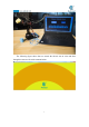
7.Draw or write in the yellow area with the mouse, you will see that the robotic arm paints what we depict on the control panel on the paper. Note that due to errors in the servo, etc., the content depicted by the arm will be slightly biased. 8.Click the dots as shown below: 9.Click on each point to see if the pen tip falls on the paper. If it is not or is suspended in the air, three parameters need to be modified. These three parameters are to fine-tune the offset of the servo.
that can make the robot work normally. 10.After modifying the three parameters to make the tip of the pen reach to the paper (do not make the tip press against the paper), click "Run" to run the control panel program. The robotic arm will paint as you write or draw in the dark yellow area with the mouse.
178
179