
5DOF Robotic Arm Kit for Ardunio Uno R3 - Tutorial
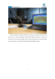
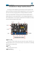
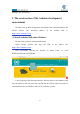
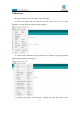
Table Of Contents
- Contents
- Components List
- Introduction of Robotic Arm
- Introduction of Adeept Arm Drive Board
- Lesson 0 Building the Arduino Development Environm
- 1.Arduino development language
- 2.Arduino program structure
- 3. The construction of the Arduino development env
- 4. Introduction of Arduino software interface
- 5.Connecting the Adeept Arm Drive Board and the co
- 6.The solution for situation that Arduino IDE cann
- 7、
- 8. Configuring the "libraries" folder of the Ardui
- Lesson 1 How to Read the Data of the Potentiometer
- Lesson 2 Controlling the Servo
- Lesson 3 Displaying Text on the OLED Screen
- Lesson 4 Saving Data with EEPROM
- Lesson 5 Servo 90 degree adjustment
- Lesson 6 How to Assemble the Robotic Arm
- Lesson 7 GUI application control mode
- Lesson 8 GwBlock graphical control mode
- Lesson 9 Potentiometer control mode
- Lesson 10 Learning mode
- Lesson 11 Processing controls robotic arm
- Lesson 12 Imitation function(Pen)
- Lesson 13 Processing controls robotic arm to write

9
Introduction of Adeept Arm Drive Board
The Adeept Arm Drive Board development board is the main component of the
robotic arm. Similar to the Arduino UNO development board, it is also an easy-to-use
open source electronic prototyping platform, including the hardware part and the
software part (Arduino IDE). The Adeept Arm Drive Board development board is
mainly composed of a microcontroller (MCU), a universal input/output interface, etc.
You can understand it as a microcomputer motherboard. We will introduce the Adeept
Arm Drive Board development board in detail.
【
1
】
Power LED
:
Power LED is used to indicate the power status of the system. The LED is on,
indicating that the system is powered on and ready to run; the LED is off, indicating
that the system is not powered on.
【
2
】
Servo
:
It is the pin interface of Servo.
【
3
】
Vin
(
6-24V
):