
5DOF Robotic Arm Kit for Ardunio Uno R3 - Tutorial
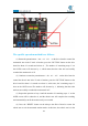
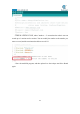
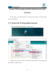
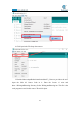
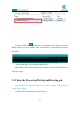
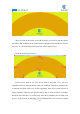
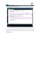
Table Of Contents
- Contents
- Components List
- Introduction of Robotic Arm
- Introduction of Adeept Arm Drive Board
- Lesson 0 Building the Arduino Development Environm
- 1.Arduino development language
- 2.Arduino program structure
- 3. The construction of the Arduino development env
- 4. Introduction of Arduino software interface
- 5.Connecting the Adeept Arm Drive Board and the co
- 6.The solution for situation that Arduino IDE cann
- 7、
- 8. Configuring the "libraries" folder of the Ardui
- Lesson 1 How to Read the Data of the Potentiometer
- Lesson 2 Controlling the Servo
- Lesson 3 Displaying Text on the OLED Screen
- Lesson 4 Saving Data with EEPROM
- Lesson 5 Servo 90 degree adjustment
- Lesson 6 How to Assemble the Robotic Arm
- Lesson 7 GUI application control mode
- Lesson 8 GwBlock graphical control mode
- Lesson 9 Potentiometer control mode
- Lesson 10 Learning mode
- Lesson 11 Processing controls robotic arm
- Lesson 12 Imitation function(Pen)
- Lesson 13 Processing controls robotic arm to write

176
7.Draw or write in the yellow area with the mouse, you will see that the robotic
arm paints what we depict on the control panel on the paper. Note that due to errors in
the servo, etc., the content depicted by the arm will be slightly biased.
8.Click the dots as shown below:
9.Click on each point to see if the pen tip falls on the paper. If it is not or is
suspended in the air, three parameters need to be modified. These three parameters are
to fine-tune the offset of the servo. In this experiment, three servo systems need to be
adjusted initially. Otherwise, the pen may not be able to write and draw, or produce
bad fonts (note that there is a certain error, these three parameters do not need to be
precise). In the process of debugging, you will find that there are several sets of data