
5DOF Robotic Arm Kit for Ardunio Uno R3 - Tutorial
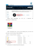
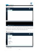

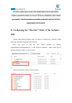
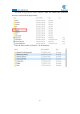
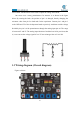
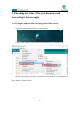
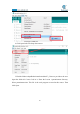
Table Of Contents
- Contents
- Components List
- Introduction of Robotic Arm
- Introduction of Adeept Arm Drive Board
- Lesson 0 Building the Arduino Development Environm
- 1.Arduino development language
- 2.Arduino program structure
- 3. The construction of the Arduino development env
- 4. Introduction of Arduino software interface
- 5.Connecting the Adeept Arm Drive Board and the co
- 6.The solution for situation that Arduino IDE cann
- 7、
- 8. Configuring the "libraries" folder of the Ardui
- Lesson 1 How to Read the Data of the Potentiometer
- Lesson 2 Controlling the Servo
- Lesson 3 Displaying Text on the OLED Screen
- Lesson 4 Saving Data with EEPROM
- Lesson 5 Servo 90 degree adjustment
- Lesson 6 How to Assemble the Robotic Arm
- Lesson 7 GUI application control mode
- Lesson 8 GwBlock graphical control mode
- Lesson 9 Potentiometer control mode
- Lesson 10 Learning mode
- Lesson 11 Processing controls robotic arm
- Lesson 12 Imitation function(Pen)
- Lesson 13 Processing controls robotic arm to write

33
Lesson 1 How to Read the Data of the Potentiometer
In this lesson, we will learn how to read the data of the potentiometer and convert
the data into an angle.
1.1 Components used in this course
Components
Quantity
Picture
Adeept Arm Drive Board
1
Micro USB Cable
1
1.2 Introduction of Potentiometer
(1) Potentiometer
The potentiometer is a resistance element with three terminals and the resistance
value can be adjusted according to a certain change law, which is equivalent to a
variable resistor. Because its role in the circuit is to obtain a certain relationship with
the input voltage (external voltage) to output Voltage, so called potentiometer.
Potentiometers can be divided into rotary potentiometers, push-pull potentiometers,
straight slide potentiometers, etc. according to the adjustment method. Our course
experiment uses a rotary potentiometer.Its three pins are showed as below:
The rotary potentiometer is an adjustable resistance element. It is composed of a
resistor and a rotating system. When a voltage is applied between the two fixed
contacts of the resistive body, the position of the contact on the resistive body is
changed by the rotating system, and a voltage that has a certain relationship with the
position of the moving contact can be achieved between the moving contact and the