
5DOF Robotic Arm Kit for Ardunio Uno R3 - Tutorial
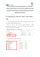
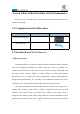
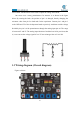
Table Of Contents
- Contents
- Components List
- Introduction of Robotic Arm
- Introduction of Adeept Arm Drive Board
- Lesson 0 Building the Arduino Development Environm
- 1.Arduino development language
- 2.Arduino program structure
- 3. The construction of the Arduino development env
- 4. Introduction of Arduino software interface
- 5.Connecting the Adeept Arm Drive Board and the co
- 6.The solution for situation that Arduino IDE cann
- 7、
- 8. Configuring the "libraries" folder of the Ardui
- Lesson 1 How to Read the Data of the Potentiometer
- Lesson 2 Controlling the Servo
- Lesson 3 Displaying Text on the OLED Screen
- Lesson 4 Saving Data with EEPROM
- Lesson 5 Servo 90 degree adjustment
- Lesson 6 How to Assemble the Robotic Arm
- Lesson 7 GUI application control mode
- Lesson 8 GwBlock graphical control mode
- Lesson 9 Potentiometer control mode
- Lesson 10 Learning mode
- Lesson 11 Processing controls robotic arm
- Lesson 12 Imitation function(Pen)
- Lesson 13 Processing controls robotic arm to write

34
fixed contact. Potentiometer can be used to adjust the voltage and current.
Our course uses a rotary potentiometer. Its structure is as shown in the figure
below. By rotating the knob, the position of pin 2 is changed, thereby changing the
resistance value from pin 2 to both ends. In the experiment. Connect pin 1 and pin 3
to the GND and 5V of the development board respectively. And then read the voltage
divided by the pin 2 of the potentiometer through the analog input pin A0. The range
is between 0V and 5V. The analog input function of Arduino has 10-bit precision, that
is, it can convert the voltage signal of 0 to 5V into an integer form of 0 to 1024.
1.3 Wiring diagram (Circuit diagram)
Figure as below
: