
5DOF Robotic Arm Kit for Ardunio Uno R3 - Tutorial
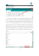
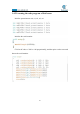
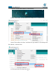
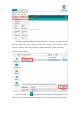
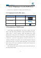
Table Of Contents
- Contents
- Components List
- Introduction of Robotic Arm
- Introduction of Adeept Arm Drive Board
- Lesson 0 Building the Arduino Development Environm
- 1.Arduino development language
- 2.Arduino program structure
- 3. The construction of the Arduino development env
- 4. Introduction of Arduino software interface
- 5.Connecting the Adeept Arm Drive Board and the co
- 6.The solution for situation that Arduino IDE cann
- 7、
- 8. Configuring the "libraries" folder of the Ardui
- Lesson 1 How to Read the Data of the Potentiometer
- Lesson 2 Controlling the Servo
- Lesson 3 Displaying Text on the OLED Screen
- Lesson 4 Saving Data with EEPROM
- Lesson 5 Servo 90 degree adjustment
- Lesson 6 How to Assemble the Robotic Arm
- Lesson 7 GUI application control mode
- Lesson 8 GwBlock graphical control mode
- Lesson 9 Potentiometer control mode
- Lesson 10 Learning mode
- Lesson 11 Processing controls robotic arm
- Lesson 12 Imitation function(Pen)
- Lesson 13 Processing controls robotic arm to write

38
Then open the serial monitor, you need to modify the displayed bit rate and the
bit rate set in the code to 115200, so that the display will not appear garbled. You can
observe the data changes corresponding to each button by rotating the buttons of A0,
A1, A2, A3, and A6. When the buttons of A0, A1, A2, and A3 are rotated, the data
change range is from 0 to 180. The data becomes smaller when rotating clockwise,
and the data becomes larger when rotating counterclockwise. When the A6 button is
rotated, the data change range is 35~90. When it is rotated clockwise, the data
becomes smaller, and when it is rotated counterclockwise, the data becomes larger.