
5DOF Robotic Arm Kit for Ardunio Uno R3 - Tutorial
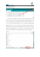
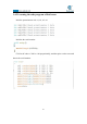
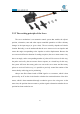
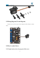
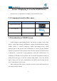
Table Of Contents
- Contents
- Components List
- Introduction of Robotic Arm
- Introduction of Adeept Arm Drive Board
- Lesson 0 Building the Arduino Development Environm
- 1.Arduino development language
- 2.Arduino program structure
- 3. The construction of the Arduino development env
- 4. Introduction of Arduino software interface
- 5.Connecting the Adeept Arm Drive Board and the co
- 6.The solution for situation that Arduino IDE cann
- 7、
- 8. Configuring the "libraries" folder of the Ardui
- Lesson 1 How to Read the Data of the Potentiometer
- Lesson 2 Controlling the Servo
- Lesson 3 Displaying Text on the OLED Screen
- Lesson 4 Saving Data with EEPROM
- Lesson 5 Servo 90 degree adjustment
- Lesson 6 How to Assemble the Robotic Arm
- Lesson 7 GUI application control mode
- Lesson 8 GwBlock graphical control mode
- Lesson 9 Potentiometer control mode
- Lesson 10 Learning mode
- Lesson 11 Processing controls robotic arm
- Lesson 12 Imitation function(Pen)
- Lesson 13 Processing controls robotic arm to write

40
Lesson 2 Controlling the Servo
In this lesson, we will learn how to control the Servo.
2.1Components used in this course
Components
Quantity
Picture
Adeept Arm Drive Board
1
Micro USB Cable
1
Servo
1
2.2 The introduction of the Servo
2.2.1 Servo
Servo motor refers to the engine that controls mechanical component operation
in the servo system. It is a kind of auxiliary motor indirect transmission device. The
servo motor is a gear motor that can rotate only 180 degrees. It is controlled by
sending pulses from the microcontroller. These pulses tell the server where to move.
The servo motor system includes housing, circuit board, non-core motor, gearing and
position detection. Servo motor is shown in the figure: