
5DOF Robotic Arm Kit for Ardunio Uno R3 - Tutorial
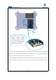

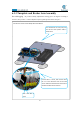
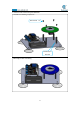
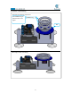
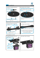
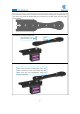
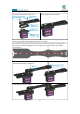
Table Of Contents
- Contents
- Components List
- Introduction of Robotic Arm
- Introduction of Adeept Arm Drive Board
- Lesson 0 Building the Arduino Development Environm
- 1.Arduino development language
- 2.Arduino program structure
- 3. The construction of the Arduino development env
- 4. Introduction of Arduino software interface
- 5.Connecting the Adeept Arm Drive Board and the co
- 6.The solution for situation that Arduino IDE cann
- 7、
- 8. Configuring the "libraries" folder of the Ardui
- Lesson 1 How to Read the Data of the Potentiometer
- Lesson 2 Controlling the Servo
- Lesson 3 Displaying Text on the OLED Screen
- Lesson 4 Saving Data with EEPROM
- Lesson 5 Servo 90 degree adjustment
- Lesson 6 How to Assemble the Robotic Arm
- Lesson 7 GUI application control mode
- Lesson 8 GwBlock graphical control mode
- Lesson 9 Potentiometer control mode
- Lesson 10 Learning mode
- Lesson 11 Processing controls robotic arm
- Lesson 12 Imitation function(Pen)
- Lesson 13 Processing controls robotic arm to write

68
Connect the 18650x2 Battery Holder to Adeept Arm Drive Board.
Once the circuit is connected, load your 18650 battery into 18650x2 Battery Holder and turn
on the switch on the Adeept Arm Drive Board. At this point, the servo will automatically rotate to
the initial state, then turn off the power and remove each servo.
In the subsequent installation processes, before fixing the servo to the rocker arm with screws, do
not rotate the rotary shaft of the servo. Otherwise, you need to follow this step again to debug the
servo.
The anode (red wire) of the
18650x2 Battery Holder
connects to the VCC interface.
The negative (black wire) is
connects to the GND interface.
And the switch is turned off.
Switch