
5DOF Robotic Arm Kit for Ardunio Uno R3 - Tutorial
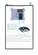

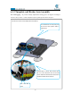
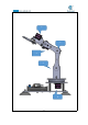
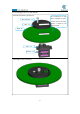
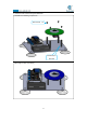
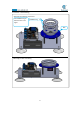
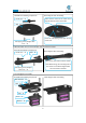
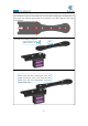
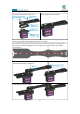
Table Of Contents
- Contents
- Components List
- Introduction of Robotic Arm
- Introduction of Adeept Arm Drive Board
- Lesson 0 Building the Arduino Development Environm
- 1.Arduino development language
- 2.Arduino program structure
- 3. The construction of the Arduino development env
- 4. Introduction of Arduino software interface
- 5.Connecting the Adeept Arm Drive Board and the co
- 6.The solution for situation that Arduino IDE cann
- 7、
- 8. Configuring the "libraries" folder of the Ardui
- Lesson 1 How to Read the Data of the Potentiometer
- Lesson 2 Controlling the Servo
- Lesson 3 Displaying Text on the OLED Screen
- Lesson 4 Saving Data with EEPROM
- Lesson 5 Servo 90 degree adjustment
- Lesson 6 How to Assemble the Robotic Arm
- Lesson 7 GUI application control mode
- Lesson 8 GwBlock graphical control mode
- Lesson 9 Potentiometer control mode
- Lesson 10 Learning mode
- Lesson 11 Processing controls robotic arm
- Lesson 12 Imitation function(Pen)
- Lesson 13 Processing controls robotic arm to write

70
Connect five servos to the Adeept Arm Drive Board.
6.1.3 Turnplate and Rocker Arm Assembly
Servo debugging(If you have already adjusted the steering gear to 90 degrees according to
Lesson 5, then you don’t need to adjust it anymore, please proceed to the next part)
`
Connect No. 1-5 servo, and increase from
No. 1-5 in the direction close to the oled
screen. Note that the direction of the Servo
interface should not be reversed
For convenience to read, only one
end of the servo power cable is
shown here.
This is the No. 1
servo