
5DOF Robotic Arm Kit for Ardunio Uno R3 - Tutorial
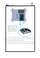

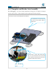
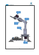
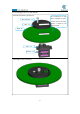
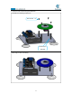
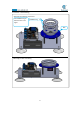
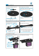
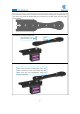
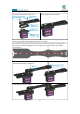
Table Of Contents
- Contents
- Components List
- Introduction of Robotic Arm
- Introduction of Adeept Arm Drive Board
- Lesson 0 Building the Arduino Development Environm
- 1.Arduino development language
- 2.Arduino program structure
- 3. The construction of the Arduino development env
- 4. Introduction of Arduino software interface
- 5.Connecting the Adeept Arm Drive Board and the co
- 6.The solution for situation that Arduino IDE cann
- 7、
- 8. Configuring the "libraries" folder of the Ardui
- Lesson 1 How to Read the Data of the Potentiometer
- Lesson 2 Controlling the Servo
- Lesson 3 Displaying Text on the OLED Screen
- Lesson 4 Saving Data with EEPROM
- Lesson 5 Servo 90 degree adjustment
- Lesson 6 How to Assemble the Robotic Arm
- Lesson 7 GUI application control mode
- Lesson 8 GwBlock graphical control mode
- Lesson 9 Potentiometer control mode
- Lesson 10 Learning mode
- Lesson 11 Processing controls robotic arm
- Lesson 12 Imitation function(Pen)
- Lesson 13 Processing controls robotic arm to write

75
Effect diagram after assembling
Effect diagram after assembling
Assemble the following components
Assemble the following components
Assemble the following components
Effect diagram after assembling
5.Take a rocker arm as in the illustration and connect it to A04
.
6. Take two rocker arm as in the illustration and connect them to A07.
7. Fix a debugged servo to A06.
Note that the center of the rocker arm is
aligned with the center of the A04.
Rocker arm x1
A04 x1
Screw the self-tapping screw just into the
rocker arm.
Self-tapping screw packaged with
servo
x2
A07 x1
Rocker arm x2
At this time, the rocker arm hasn’t been
fixed. When fixing, the mounting hole of
the rocker arm should be aligned with
the round hole on the A07.
Self-tapping screw packaged
with servo
x2
M2*10 Screw x2
A06 x1
A09 x1
Servo x1
M2 Nut x2