
5DOF Robotic Arm Kit for Ardunio Uno R3 - Tutorial
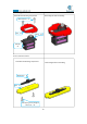
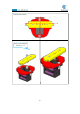
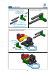
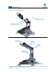
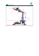
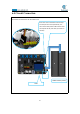
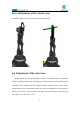
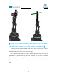
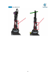
Table Of Contents
- Contents
- Components List
- Introduction of Robotic Arm
- Introduction of Adeept Arm Drive Board
- Lesson 0 Building the Arduino Development Environm
- 1.Arduino development language
- 2.Arduino program structure
- 3. The construction of the Arduino development env
- 4. Introduction of Arduino software interface
- 5.Connecting the Adeept Arm Drive Board and the co
- 6.The solution for situation that Arduino IDE cann
- 7、
- 8. Configuring the "libraries" folder of the Ardui
- Lesson 1 How to Read the Data of the Potentiometer
- Lesson 2 Controlling the Servo
- Lesson 3 Displaying Text on the OLED Screen
- Lesson 4 Saving Data with EEPROM
- Lesson 5 Servo 90 degree adjustment
- Lesson 6 How to Assemble the Robotic Arm
- Lesson 7 GUI application control mode
- Lesson 8 GwBlock graphical control mode
- Lesson 9 Potentiometer control mode
- Lesson 10 Learning mode
- Lesson 11 Processing controls robotic arm
- Lesson 12 Imitation function(Pen)
- Lesson 13 Processing controls robotic arm to write

94
6.5 Combinations of the robotic arm
Assemble method (except the front part of the robotic arm).
6.6 Adjustment of the robot arm
Before starting to exert the function, we need to test whether there are problems
with the assembly of the robotic arm.When you connect all the servos mounted on the
robot arm to the Adeept Arm Drive Board correctly and turn on the power switch
(using battery power), the attitude of the robot arm is perpendicular to the ground as
follows ((it may not be able to achieve the effect shown in the picture when powered
on, a little error is allowed to exist).