
5DOF Robotic Arm Kit for Ardunio Uno R3 - Tutorial
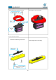
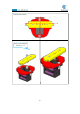
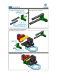
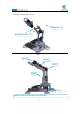
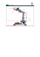
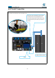
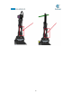
Table Of Contents
- Contents
- Components List
- Introduction of Robotic Arm
- Introduction of Adeept Arm Drive Board
- Lesson 0 Building the Arduino Development Environm
- 1.Arduino development language
- 2.Arduino program structure
- 3. The construction of the Arduino development env
- 4. Introduction of Arduino software interface
- 5.Connecting the Adeept Arm Drive Board and the co
- 6.The solution for situation that Arduino IDE cann
- 7、
- 8. Configuring the "libraries" folder of the Ardui
- Lesson 1 How to Read the Data of the Potentiometer
- Lesson 2 Controlling the Servo
- Lesson 3 Displaying Text on the OLED Screen
- Lesson 4 Saving Data with EEPROM
- Lesson 5 Servo 90 degree adjustment
- Lesson 6 How to Assemble the Robotic Arm
- Lesson 7 GUI application control mode
- Lesson 8 GwBlock graphical control mode
- Lesson 9 Potentiometer control mode
- Lesson 10 Learning mode
- Lesson 11 Processing controls robotic arm
- Lesson 12 Imitation function(Pen)
- Lesson 13 Processing controls robotic arm to write

95
【
If your robot arm is assembled and turned on, it is not what it
looks like in the picture above, then how do you adjust it?
】
1.First, you need to re-download the code used in lesson 5: Servo90.ino. Observe
if the robot arm is close to the one in the picture above.
2.If it does not work, then you need to manually disassemble the robot arm for
adjustment, is to operate with the power on, generally you just need to manually
adjust the A07 section in the figure below, remove it, and then connect the upper and
lower sections of the robot arm vertical ground, and then install the A07 on to fix
them.