www.adeept.
www.adeept.com Warning Please pay attention to the following issues when purchasing or using the product: There are small components included in this kit. Swallowing mistakenly or misoperation can cause serious infection and be even fatal. When an accident occurs, please seek medical assistance immediately. Please place the product in a safe place where an under-6-year-old cannot touch, who should not use or approach the product. Juveniles should use the product with their parents.
www.adeept.com Copyright This user manual and code can be used for learning, DIY, refitting, etc., except for commercial purpose. The Adeept Company owns all rights of contents in the manual, including but not limited to texts, images, data, etc. Any distribution or printing should be implemented with the permission of the Company, or it will be deemed illegal.
www.adeept.com contents 1. Components List.............................................................................................................................. 1 1.1. Acrylic Plates........................................................................................................................ 1 1.2. Machinery Parts................................................................................................................... 3 1.3. Electronic Parts.......................................
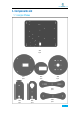
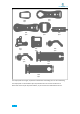
www.adeept.com 1. Components List 1.1.
www.adeept.com A10 1pcs A09 1pcs A11 1pcs A14 2pcs A13 1pcs A12 1pcs A15 1pcs A17 1pcs A16 1pcs A18 1pcs A19 1pcs The acrylic plates are fragile, so please be careful when assembling them in case of breaking. The acrylic plate is covered with a layer of protective film. You need to remove it first. Some holes in the acrylic may have residues, so you need to clean them before the use.
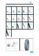
www.adeept.com 1.2. Machinery Parts M2.5*11 M2 M3 M3 Nut Nut Lock Nut Copper Standoff M2*10 X11 X7 X3 X2 X9 M2.5*7 M3*5 M3*8 M3*12 Screw Screw M3*18 Screw www.adeept.com www.adeept.com www.adeept.com www.adeept.com www.adeept.com Screw Screw Screw X5 X4 X18 X5 X1 M3*10 M3*8 M3*15 M2*18 M3*30 www.adeept.com www.adeept.com www.adeept.com www.adeept.com www.adeept.com Countersunk Head Screw X2 Copper Standoff Nylon Standoff X1 X4 Screw X2 Nylon Standoff X5 www.
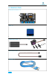
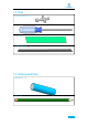
www.adeept.com 1.3.
www.adeept.com 1.4. Tools Cross Socket Wrench X1 Large Cross-head Screwdriver Ribbon X1 X1 Winding Pipe X1 1.5.
www.adeept.com 2.Introduction of Robotic Arm Nowadays, under the progress of science and technology, the biggest difference between a robotic arm and a human arm lies in flexibility and strength. That is, the biggest advantage of the robotic arm is that normally it can repeat the same motion without feeling tired. Today Adeept recommends a robotic learning kit to learn how to assemble a robotic arm and learn how to write the code to control the robotic arm to perform the specific motions.
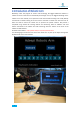
www.adeept.com The following figure shows that we control the robotic arm to write and draw through the mouse with serial communication. We have added the learning and memory function to the robotic arm. We let the robotic arm to record the manually controlled mechanical movements we made, and the robotic arm can learn repeatedly, such as repeat moving the object, repeat drawing the same graphic, repeat keyboard input and repeat turning book pages.
www.adeept.com 3.Arduino and Processing Environment Installation More about building up Arduino development environment please check this video More learning videos please click on http://www.adeept.com/video/ Let's take the Windows 64-bit system as an example (the Arduino IDE also supports MAC and Linux). First open the browser and enter the URL https://www.arduino.cc/en/Main/Software and you will see the following interface. Click “JUST DOWNLOAD”.
www.adeept.com Run the downloaded file. Click “I Agree”. Click “Next”.
www.adeept.com Leave the installation path as default, click "Install". Then enter the installation process, please wait. If the option pops up during the installation process, please select "Install".
www.adeept.com When the installation is complete, click "Close". After the installation is complete, you can see the icon of the Arduino IDE on your computer desktop. Click to run Arduino, the following interface will appear.
www.adeept.com Next we need to install the driver program of the Adeept Robotic Arm Drive Board. We provide driver programs for 4 systems, Windows, Android, Linux and Mac in the package. We need to select the corresponding driver installation according to the system. Let's take the Windows system as an example. Firstly connect Adeept Robotic Arm Drive Board to the computer with a USB cable. Then open the package, find out the CH341SER_Windows.exe application, and run the program.
www.adeept.com Let's write a simple program that lights up the LEDs on theAdeept Robotic Arm Drive board and lets them flash. Code: Next we connect the Adeept Robotic Arm Drive Board to the computer with a USB cable.
www.adeept.com Next, go back to the Arduino IDE interface and select the model of the control board.
www.adeept.com When finish selecting, upload the code to Adeept Robotic Arm Drive Board by clicking "Upload". When the code is successfully downloaded to Adeept Robotic Arm Drive Board, you can see the LED flashes. More details about the download and usage of Processing, please click on this video More learning videos please click on http://www.adeept.com/video Open your browser and enter the URL www.processing.
www.adeept.
www.adeept.com When finish downloading, you will get a compressed file "processing-3.4-windows64.zip".
www.adeept.com After extracting this file, you can get the following file, just click to run processing, it can be run directly without installation.
www.adeept.com Let's write a simple code that implements the following functions "Change the variable to create a moving line. When the line moves out of the window edge, the variable becomes 0 and the line goes back to the bottom of the screen.
www.adeept.com Click “Run”.
www.adeept.com Running effect is as follow.
www.adeept.com 4 Assembly 4.1. PedestalAssembly. 1.Fix four Sucking Discs on the four corners of A01.
www.adeept.com 2.Fix OLED to drive Assemble the following components M2*18 Screw x2 M2.5*11 cooper stands x2 OLED M2 Nut x2 Effect diagram after assembling OLED should be installed in the Robotic arm drive HAT.
www.adeept.com 3.Fix 18650x2 Battery Holder to A01. Assemble the following components M3*10 Countersunk Head Screw x2 The wires of 18650x2 Battery Holder are near inside.
www.adeept.com 4.Fix four M3*15 nylon Standoffs to A01.
www.adeept.com 5.Fix Adeept UNO R3 Board to M3*15 nylon Standoff.
www.adeept.com 6. Fix four M3*30 Nylon Standoffs to A01.
www.adeept.com Connect the 18650x2 Battery Holder to Adeept Arm Drive Board. The anode (red wire) of the 18650x2 Battery Holder connects to the VCC interface. The negative (black wire) is connects to the GND interface. And the switch is turned off. Switch Once the circuit is connected, load your 18650 battery into 18650x2 Battery Holder and turn on the switch on the Adeept Arm Drive Board.
www.adeept.com 4.2. Install and Remove Batteries Take out 2 ribbons and 2 batteries. Roll one end of the ribbon to let through a battery and fix. Insert the batteries into the rings-ribbon closer to the anode. Install the batteries into the holder based on the pole. To remove the batteries, just pull the ribbon and take them out.
www.adeept.com 4.3. Turnplate and Rocker Arm Assembly .Servo debugging. Connect five servos to the Adeept Arm Drive Board. For convenience to read, only one end of the servo power cable is shown here. ` Connect the servo 1 to 5, sequentially increase by the direction near the OLED screen. Pay attention to the direction of the servo interface.
www.adeept.
www.adeept.com 2. Fix a debugged servo to A02 and A03. Assemble the following components M2*10 Screw A03 A02 x1 x1 x1 Servo x1 M2 Nut Effect diagram after assembling 32 x1 For convenience to read, A02 is displayed in green, and the color of all acrylic sheets is subject to the actual product.
www.adeept.com 3. Then fix A02 to M3*30 Nylon Standoff.
www.adeept.com 4. Assemble 51108 Bearing. Assemble the following components Put 51108 Bearing on A03 as shown in the figure.
www.adeept.com 5.Take a rocker arm as in the illustration and connect it to A04. Assemble the following components Rocker arm A04 x1 Effect diagram after assembling Note that the center of the rocker arm is aligned with the center of the A04. x1 Screw the self-tapping screw just into the rocker arm. Self-tapping screw packaged with servo x2 6. Take two rocker arm as in the illustration and connect them to A07.
www.adeept.com 8. Then fix one end of A07 to the servo on A06. First install the rocker arm on the A07 into the servo. When installing, the mounting hole of the rocker arm should be aligned with the round hole on the A07. Install it at the angle shown below. Assemble the following components M2.5*7 Screw x1 A07 Effect diagram after assembling Please note that when installing the rocker arm, connect the servo to the robot drive Hat. The robot drive Hat will automatically check the servo angle.
www.adeept.com 9. Fix a debugged servo to A10. Assemble the following components M2*10 Screw x2 A10 Effect diagram after assembling x1 A09 x1 Servo x1 M2 Nut x2 10. Then fix the other end of the A07 to the servo on the A10. First install the rocker arm on the A07 into the servo. When installing, the mounting hole of the rocker arm should be aligned with the round hole on the A07. Install it at the angle shown below. Assemble the following components A07 M2.
www.adeept.com 11. Then fix A06 to A04.
www.adeept.com 12.Connect A05 with A08 and A11. Assemble the following components M3 Lock Nut x2 A08 A11 x1 x1 A05 M3*12 Screw x1 x2 Do not tighten between M3 Lock Nut and M3*12 Screw. Allow rotation between A05 and A08, also A08 and A11.
www.adeept.com 13. Fix A05 to A04.
www.adeept.com 14. Fix the rocker arm under A04 with the servo on A02. The angle when the rocker arm is installed into the servo is as shown below.
www.adeept.com Effect diagram after assembling Then fix the rocker arm to the servo with the fixing screw packaged with servo.
Effect diagram after assembling www.adeept.
www.adeept.com 4.4.Play 1 Fix A18 between A10 and A11. Assemble the following components M3 Nut x2 M3*8 Screw A18 x1 Effect diagram after assembling 44 x2 Choose A18 or A19 according to the actual size of the pen.
www.adeept.com Fix the pen with A18. Assemble the following components Pen M3 Nut x1 x1 M3*12 Screw x1 Effect diagram after assembling The tip of the pen should be 60 mm away from A18.
www.adeept.com 4.5.Play 2 1. Fix one M3*8 Copper Standoff to A15. Assemble the following components Effect diagram after assembling M3*8 Copper Standoff A15 Install it in strict accordance with the position shown in the figure. Do not mount the M3*8 Copper Standoff on the other side of the A15. M3*18 Screw x1 2. Fix a debugged servo to A15.
www.adeept.com 3. Fix one rocker arm of the servo to A17. Assemble the following components Rocker arm A17 Effect diagram after assembling x1 x1 Self-tapping screw packaged with servo x1 4. Assemble A16 and A17. Install A16 and A17 as shown below. A16 A17 Assemble the following components M3 Lock Nut x1 A16 M2.5*7 Screw Effect diagram after assembling x1 x1 Do not tighten the M3 Lock Nut to ensure that the A16 can rotate.
www.adeept.com 5.Fix a debugged servo to A12. Assemble the following components M2*10 Screw A12 Effect diagram after assembling x2 x1 Servo x1 M2 Nut x2 6. Fix a rocker arm to A13.
www.adeept.com 7. Fix the rocker arm on the A13 to the servo on the A12. Install as shown below.
www.adeept.com 8. Fix one A14 with two M3*40 Nylon Standoffs. Assemble the following components M3*8 Screw x2 A14 x1 M3*40 Nylon Standoff x2 9. Complete assembly of the clamp section.
www.adeept.com Install the clamp section on the robotic arm. Assemble the following components M3*8 Screw M3*30 Nylon Standoff x2 x1 Effect diagram after assembling Servo4 Servo5 Servo3 Servo2 Servo1 Number each servo to prepare for the circuit connection.
www.adeept.com 66.
www.adeept.com 4.6 Circuit Connection Connection of each devices for the robotic arm: Insert the servo numbered in the last step into the port here correspondently. The color of the three power cables of the servo corresponds to the port color (as shown on the left).
www.adeept.com 5.Combinations of the robotic arm. Assemble method (except the front part of the robotic arm). In 90 degrees when powered on Before starting to exert the function, we need to test whether there are problems with the assembly of the robotic arm. In the matching code, AdeeptArmInitializationCode.ino is the code for testing the robotic arm to adjust to 90 degrees when powered on.
www.adeept.com 6.Functions of the robotic arm We provide three examples to complete the function of carrying objects. You can give full play to your creativity to develop new functions. Click on http://www.adeept.com/forum to explore and learn with us. 6.1. Potentiometer control mode Rotate the potentiometer on the driver board to control the robotic arm to clamp objects. Code AdeeptPotentiometerControlArm.ino Specific function descriptions.
www.adeept.com Then connect the robotic arm to the computer with the USB cable. (Note: Do not turn on the power supply to prevent damages of swinging arm. Also pay attention to this in the subsequent operation).
www.adeept.com Next, click on "Tools" -> "Port:" -> "COM7" (note that the COM7 here may be recognized differently on different computers, it can be COM1, COM2 or COM3 and so on.
www.adeept.com Then click "Upload" to upload the program to the Adeept Robotic Arm Drive board. When the software prompts the following information, the code upload is complete.
www.adeept.com Next, unplug the USB cable connected to the robotic arm. Note: Do not turn on the power of the arm after downloading the program.
www.adeept.com Gently support the robotic arm with your hand to prevent swinging arm. Turn on the power, and then rotate the four potentiometers on the driver board to control the arm to clamp and carry objects. The rotation angle of Servo5 is set in the code. 6.2.Learning mode Function introduction Rotate the potentiometer on the driver board to adjust the movement of the robotic arm. Use the touch button to record the movement of the arm.
www.adeept.com at the current moment, and so on, you can gradually make it record the track you need. It can record 200 motions in maximum at a time. You can change the number of motions to be recorded in the program. When the data recorded by UNO reaches the motion data set by the program, the robotic arm will automatically repeat the recorded motions. At this time, when the system is restarted, the robotic arm will still in learning mode.
www.adeept.com Before downloading the program, you have to plan how many motions to record this time.
www.adeept.com Take the recording of 10 times of motion data as an example, download the code to the UNO board, firstly connect the robotic arm to the computer with the USB cable, and then select the development board model and port.
www.adeept.com After the program is successfully uploaded, unplug the USB cable connected to the robotic arm.
www.adeept.com Next, rotate the potentiometer on the driver broad to the center as shown below: After completing the above preparations, gently support the robotic arm and then turn on the power. You will see the working status of the current situation and the number of the remaining motions the robotic arm needs to be record display on the OLED. Adjust the potentiometer to move the robotic arm.
www.adeept.com 6.3. Processing controls servo If the code hasn’t been used in processing before, the library file controlP5 needs to be added. Then search controlP5.
www.adeept.com Finally click Install. Specific function introduction: Control the robotic arm to carry objects through Processing with serial communication. Processing interfaces are as follows. Click "keyboard" the following interface will appear. Next, press the corresponding button on the keyboard to control the arm. "Q" and "W" control servo4 (Gripper), "E" and "R" control servo5 (Rotate), "T" and "Y" control servo3 (Elbow), "U" and "I" control servo2 ( Shoulder), "O" and "P" control servo1 (Base).
www.adeept.com At this point, click the corresponding button, the robotic arm will make the corresponding movement. "Gripper+" and "Gripper-" control the servo5, "Rotate+" and "Rotate-" control the servo4, "Elbow+" and "Elbow-" control the servo3, "Shoulder+" and "Shoulder-" control the servo2, " Base+” and “Base-” control the servo1. Operating steps: Open the file AdeeptArmRobot.
www.adeept.com Next, connect the robotic arm to the computer with the USB cable.
www.adeept.com Click "Upload" to upload the code to UNO, as shown below: After downloading, close AdeeptArmRobot.ino. Note that the arm is still connected to the computer with the USB cable. Rotate the arm to the position as shown in the figure below (the initialization value is set in the program. If the arm is not in the position as shown below before powered on, it will swing and may cause damages when is energized), and then turn on the power.
www.adeept.com Next open AdeeptProcessingArmRobot.
www.adeept.com The control interface can then be used to control the robotic arm.
www.adeept.com 6.4. Imitation function Function introduction: The motion track can be divided specifically if rotate the potentiometer A0, A1 and A2 to adjust the robotic arm. Press the touch button every time the arm moves (how much distance to move here can be determined by you. The shorter the moving distance, the more data the robotic arm records, and the more it imitates the movement similarly).
www.adeept.com Step 2: Connect the robotic arm to the computer with the USB cable. (Note: Do not turn on the power supply when downloading the program to prevent damages of swinging arm.) Select the board model and port in Arduino IDE. Step 3: Click “Upload” to upload the code to UNO of the robotic arm.
www.adeept.com Step 4: Unplug the USB cable connected to the robotic arm and turn on the power. You can implement the imitation function to make keyboard input and turn e-book pages.
www.adeept.com 6.5. Processing controls robotic arm to write and draw Function introduction: The control interface of Processing is as shown below: Draw or write in the yellow area with the mouse, you will see that the robotic arm paints what we depict on the control panel on the paper. Note that due to errors in the servo, etc., the content depicted by the arm will be slightly biased. Operating steps: Open AdeeptWritingAndDrawing.ino, the following interface will appear.
www.adeept.com Connect the robotic arm to the computer.
www.adeept.com Click "Upload" to upload the code to the UNO board. Close the Arduino IDE after completed download. Do not unplug the USB cable connected to the robotic arm. Turn on the power supply and open the program AdeeptProcessingWritingAndDrawing.
www.adeept.com Next, fine-tune the offset of the servo. In this experiment, the initial adjustment of the three servos is required. Otherwise, the pen may not be able to write and draw or it may generate bad typeface.
www.adeept.com Click the dots as shown below: click each dot to see if the tip of the pen falls on the paper. If it’s not or suspend in the air, you need to modify the three parameters. (Note that there’s certain error existing, the three parameters are not required to be precise. During the debugging, you will find that several sets of data can make the robotic arm work normally.
www.adeept.com 7.Afterword Thanks for purchasing our product and reading the manual! If you spot any errors or have any ideas or questions for the product and this guide, welcome to contact us! We will correct them if any as quickly as possible. For more information about Arduino, Raspberry Pi, smart car robot, or robotics, etc., please follow our website www.adeept.com.
www.adeept.