
Specifications

IX.
GENERAL SPECIFICATIOWS:
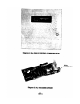
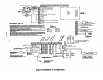
A. No. 4160.12 Control/Commnicator
See Diagrams 4 and 9.
1.
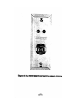
Physical:
Width:
-
14" (36.5 cm)
-i
.
Dept I
12" (30.5 cm)
3.3"
(
8.4 cm)
2.
Electrical:
Voltage:
18 VAC (from No. 1323 30VA Plug-in Transformer)
Maximum Permissible Resistance (per zone): 600 Ohms (plus end-
of-line resistor:
1000
Ohms)
Zone Response: 250 msec (normal), 15 msec (fast)
Bell Relay (Wet) Output:
SPST, Maximum Output: 2A @ lPV.DC
12V.DC Requlated Output:
Continuous Power for Accessories: 300 mA
Continuous Power for Smoke Detectors: Same 300 mA pool
defined above.
6.5 DC Regulated Output
Continuous Power for Console and Keypads: 675 mA
12 V.DC Siren Pouer Output: On Alarm: 2A max.
Arm/Disarm Status Output:
Armed: OV
Disarmed: +12 V.DC, 10 mA
Fuses:
Three fuses -
No. 90-2: 2A 6V auxiliary power for consoles/keypads.
No. 90-12: 3A 12V output for optional siren driver
(No. 4165) and speaker power, auxiliary current, fire
detectors, bell power
No. 90-17:
4A for battery protection.
Standby:
12V Sealed Lead Acid Rechargeable Battery,
2.5 AH
(No.
584)
or
5
AH (No.
BPl)
I
AXIMUM STANDBY TIMES WITH
VARIOUS AUX,ILIARY,
SMOKE/COMBUSTION
DETECTOR. AND CONSOLE CONTINUOUS LOAD (ASSUMES ONE SECURITY
I
CONSOLE PLUS ONE REMOTE KEYPAD, NO ALARMS1 *
,MODEL MA. 0 I
50 I
100 I 150 I 200 I 250 I
300
4160SB (2.5 AH) HRS. 7.5 I
1:::
I 5.9 I 5.3 I 4.8 I 4.3
I
4
4160XB ( 5 AH) HRS. 15
I
I
11.8
I
10.5 I 9.5
I
8.6
I
8
_ Battery normally need not be replaced for at least 5 years.
628-52
729