ADEMCO 6272 Series TouchCenter Keypads Installation and Setup Guide 800-04701V1 2/10 Rev.
Table of Contents • • • • • • • • • • • • • • • • • • • • • • • • • • • • • • • • SECTION 1 – General Information ............................................ 1–1 About the TouchCenter................................................................. 1–1 System Features........................................................................ 1–1 Security.......................................................................................... 1–1 Setup ........................................................
Table of Contents (Cont'd) Central Station Setup.............................................................. 5–12 ECP Address Selection ............................................................ 5–13 Options and Operating Modes................................................. 5–13 EN50131 Display..................................................................... 5–13 Safe Mode ................................................................................ 5–15 Automatic Entry.........................
Conventions Used in This Manual • • • • • • • • • • • • • • • • • • • • • • • • • • • • • • • • Before you begin using this manual, it is important that you understand the meaning of the following symbols (icons) and text note. notes include specific information that must be followed if you are UL These installing this system for a UL Listed application.
S E C T I O N 1 General Information • • • • • • • • • • • • • • • • • • • • • • • • • • • • • • • • In This Section ♦ About the TouchCenter ♦ Compatibility ♦ System Features ♦ Safe Mode • • • • • • • • • • • • • • • • • • • • • • • • • • • • • • • • About the TouchCenter The 6272 Series graphical touch-screen keypads are Advanced User Interface (AUI) devices, which combine security and home control.
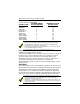
TouchCenter Installation and Setup Guide be used with each system, and the minimum alarm panel software revision level for compatibility. MAXIMUM NUMBER MINIMUM SOFTWARE OF TOUCHCENTERS REVISION LEVEL ALARM SYSTEM VISTA-15P 2 3.0 VISTA-20P 2 3.0 VISTA-20P 4 5.0 VISTA-20PS 2 3.0 VISTA-20PS 4 5.0 VISTA-21IP 4 1.0 VISTA-128BP 3 2.4 VISTA-128FBP 3 1.6 VISTA-250BP 3 2.4 VISTA-250FBP 1 1.5 VISTA-250FBP 3 2.
S E C T I O N 2 Mounting and Wiring • • • • • • • • • • • • • • • • • • • • • • • • • • • • • • • • In This Section ♦ Mounting the TouchCenter Mounting Plate ♦ Wiring the TouchCenter • • • • • • • • • • • • • • • • • • • • • • • • • • • • • • • • Mounting the TouchCenter Mounting Plate The TouchCenter should be mounted using the following criteria: • • • The TouchCenter must be mounted indoors should be mounted at eye level for easy viewing by the user should not be mounted in areas of high condensatio
TouchCenter Installation and Setup Guide MOUNTING SCREWS (4) (TYP) WALL SURFACE BREAK OFF LOCKING TAB DO NOT DISCARD WALL MOUNTING PLATE 6272-003-V0 Figure 1. Mounting the TouchCenter Mounting Plate Wiring the TouchCenter Connect TouchCenter in parallel with keypads and other peripheral devices using the keypad data (ECP) bus. Determine wire gauge by referring to the Wire Run Length/Gauge table below.
SECTION 2: Mounting and Wiring To wire, see the Summary of Connections diagrams at the back of this guide, or the appropriate Systems Interconnection Diagram provided, and follow the instructions below. The TouchCenter draws up to 305mA (on models 6272CV, 6272CBV, 6272CSV . If you are planning to power it from your panel’s Aux Power output, check your panel’s Installation and Setup Guide and verify that this device and others do not exceed your panel's Aux Power output capability.
TouchCenter Installation and Setup Guide 2. Connect ground to the TouchCenter using step a or b below. a. If powering the keypad from the control panel, connect the AUX – terminal of the control panel to the – terminal block position (GND terminal of the TouchCenter (black wire)). b. If powering the keypad from a supplementary power supply, connect the AUX – terminal of the control panel to the (–) terminal of the supplementary power supply (black wire).
S E C T I O N 3 Front Panel LEDs and Navigation Icons • • • • • • • • • • • • • • • • • • • • • • • • • • • • • • • • In This Section ♦ Front Panel LEDs ♦ Panel Fault Displays ♦ Navigation Icons • • • • • • • • • • • • • • • • • • • • • • • • • • • • • • • • Front Panel LEDs The TouchCenter has three LEDs labeled - ARMED, READY and MESSAGE. The ARMED LED is red, READY LED is green and MESSAGE LED is yellow. Each LED's on and off state has different meanings as described below.
TouchCenter Installation and Setup Guide Navigation Icons To aid in the navigation through TouchCenter screens, a set of userfriendly icons has been provided. The appearance, function, and location of these icons is described below: ICON LOCATION "Home" screen Allows you to record and retrieve voice messages. "Home" screen Allows you to turn certain devices on and off (if installed and programmed by your installer.) "Home" screen 3–2 FUNCTION Accesses "Security" screen.
SECTION 3: Front Panel LEDs and Navigation Icons Panel Fault Displays The “Security” screen displays an Icon(s) if a panel fault(s) occurs. The fault Icon is displayed to the left of the Panic button. The following Icons may be shown as applicable to your system: ICON MEANING AC Loss – The system is not receiving AC power. Bell Failure – The system bell or siren has a problem. Note: This Icon will be displayed when interfacing with residential panels only.
TouchCenter Installation and Setup Guide 3–4
S E C T I O N 4 Initial Setup • • • • • • • • • • • • • • • • • • • • • • • • • • • • • • • • In This Section ♦ Programming the Control Panel ♦ TouchCenter Initialization • • • • • • • • • • • • • • • • • • • • • • • • • • • • • • • • Programming the Control Panel The TouchCenter will not be fully operational unless its address in the control panel has been enabled for an alpha console, AUI type device, and assigned to a partition (where applicable).
TouchCenter Installation and Setup Guide Notes: • If multiple TouchCenters are being used, they must be set to addresses 1, 2, and X (where X equals any address from 3 through 30. Only one AUI type device may be assigned to an address from 3 through 30 on commercial control panels. • The TouchCenter should not be assigned as a Master Console. If the TouchCenter is assigned as a Master Console, partitions must be controlled from the Partition screen or using the Console Emulation Mode.
SECTION 4: Initial Setup TouchCenter Initialization Power Up When initially powered, the screen displays the boot sequence as it is performed. After it is determined what services are available, the screen displays the "Set ECP Address" screen. SCREEN ACTION If the system is incorporating only one TouchCenter, leave the address set to 1 and press the OK button. The boot-up process will continue until completion.
TouchCenter Installation and Setup Guide 4–4
S E C T I O N 5 Setup • • • • • • • • • • • • • • • • • • • • • • • • • • • • • • • • In This Section ♦ ♦ Setup Display & Audio Setup ♦ ♦ Slide Show Setup System Setup • • • • • • • • • • • • • • • • • • • • • • • • • • • • • • • • Setup Setup allows you to make changes to the way your TouchCenter is operating. You may access Display & Audio Setup, System Setup (if enabled by your system installer), and Slideshow Setup from the "Setup" screen by pressing the corresponding button.
TouchCenter Installation and Setup Guide Adjust the Brightness You may adjust the brightness settings by pressing your finger on the slide bar associated with the "Brightness" scale and doing the following: To increase brightness, move the slide bar above the current brightness setting. To decrease brightness, move the slide bar below the current brightness setting.
SECTION 5: Setup Display & Audio Setup Operating Modes Operating modes allow you to turn the TouchCenter chime mode on or off. Additionally, you may also turn the voice mode on or off. The operating modes provide the following features: • Chime Mode – When selected, a request is sent to the alarm panel requesting that the panel chime the TouchCenter whenever a change in zone status occurs.
TouchCenter Installation and Setup Guide SCREEN ACTION 5. Touch the Voice Mode button to turn the Voice Mode on or off. A checkmark appears in the button when the Voice Mode is “ON”. Note that if the Chime Mode and Voice Mode are both selected, the Voice Chime button will automatically be selected. Press the “HOME” or “BACK” button after making your selection. When the TouchCenter exits the “Operating Modes” screen, your selection is saved.
SECTION 5: Setup SCREEN ACTION 4. To select a specified language, choose English, French Canadian, Portuguese, South American Spanish, Italian and European Spanish). Once the language is selected, the keypad will revert back to "Home" screen with the selected language applied. Backlight Off Activation Time When the TouchCenter is left idle, it will automatically turn the backlight off after the selected backlight off time has expired (unless “Never” option is selected).
TouchCenter Installation and Setup Guide SCREEN ACTION 3. Press either the "Home", "Back," "Home Setup" or "RESET Home Setup" buttons. A Settings Changed! pop-up window is displayed asking “Remember New Settings?“ Select Yes to save the change or No to discard the change. When the update is complete, depending on which selection you made, ( "Home", "Back," "Home Setup" or "RESET Home Setup") the TouchCenter will go to it's respective selected screen.
SECTION 5: Setup SCREEN ACTION 3. Press either the "Home", "Back," "Home Setup" or "RESET Home Setup" button. A Settings Changed! pop-up window is displayed asking “Remember New Settings?“ Select Yes to save the change or No to discard the change. When the update is complete, depending on which selection you made, ( "Home", "Back," "Home Setup" or "RESET Home Setup") the TouchCenter will go to it's respective selected screen.
TouchCenter Installation and Setup Guide SCREEN ACTION 3. Press either the "Home", "Back," "Home Setup" or "RESET Home Setup" button. A Settings Changed! pop-up window is displayed asking “Remember New Settings?“ Select Yes to save the change or No to discard the change. When the update is complete, depending on which selection you made, ("Home", "Back," "Home Setup" or "RESET Home Setup") the TouchCenter will go to it's respective selected screen.
SECTION 5: Setup IMPORTANT: Do not use an abrasive cleaning agent or abrasive cloth when cleaning the TouchCenter or damage to the touch screen may occur. The Emergency screen cannot be accessed while running in the clean screen mode. Routine Care • • • Treat the components of the security system as you would any other electrical equipment. Do not slam sensor-protected doors or windows in the vicinity of the keypad.
TouchCenter Installation and Setup Guide SCREEN ACTION 5. When completed, press either the "Home", or "Back" button. A Settings Changed! pop-up window is displayed asking “Remember New Settings?“ Select Yes to save the change or No to discard the change. After selecting Yes or No, the TouchCenter will revert back to the either Home screen or Display and Audio Setup screen, depending on the selection made in Step 4.
SECTION 5: Setup Slide Show Setup The 6272 Keypad offers a Slide Show Feature. How to customize these features will be described in this section. To set up the Slide Show, press the Setup button on the "Home" screen and do the following: SCREEN ACTION 1. Press the Slideshow Setup button. The "Slideshow Setup" screen is displayed. 2. Insert your personal media card. The first image will be displayed and a list of stored images will appear on the screen. 3.
TouchCenter Installation and Setup Guide The following icons are displayed on the "Slideshow Setup" screen: Preview Previous image Next image Add/Remove image from slide show Set image to home screen wallpaper System Setup Central Station Setup To Access the “Central Station” screen perform the following: 1. Press the Setup button on the “Home” screen. The “Setup” screen is displayed. SCREEN ACTION 2. Press the System Setup button. The “System Setup” screen is displayed.
SECTION 5: Setup SCREEN ACTION The "System Setup" screen is displayed. ECP Address Selection After enabling addresses in the control panel using an alpha-keypad, power-up each TouchCenter one at a time, and set its address to one of the addresses you enabled in the control panel. Otherwise, access the Central Station screen then follow the procedure to change the address on the unit. To change the address, perform the following. SCREEN ACTION 1.
TouchCenter Installation and Setup Guide and the "Armed" and "Ready" LEDs turn OFF. The "Return to Homepage" time setting changes to 30 seconds and the time will be non-selectable. • The Security, Message and Lighting screen will not display system status until an authorized user code is entered. • The "Setup" menu will not display system status until an authorized user code is entered. The system "Operating Modes" menu allows you to access "Normal Mode", "Safe Mode" and "Demo Mode".
SECTION 5: Setup Safe Mode The Safe Mode may be automatically entered by the TouchCenter program on a communication failure or may be entered manually on command. The following paragraphs describe these entry processes. Automatic Entry In the rare event that the TouchCenter cannot successfully communicate in its graphic mode with the control panel, the TouchCenter presents you with a message of “Problems detected. Start Keypad in Safe Mode?” and requests a “Yes” or “No” response.
TouchCenter Installation and Setup Guide SCREEN ACTION 5. Select Safe Mode and then press the Apply button. The “Warning” message "Keypad will reset to activate changes" is displayed. 6. Press the OK button. The TouchCenter will reset and restart in the Safe Mode. Operating in the Safe Mode While in the Safe Mode, the Home screen will display the Security Button, Panic Button, and Message Button.
SECTION 5: Setup User and Installation Guides. You can perform almost all functions that you can perform from a standard non-graphic alpha keypad. • You can depress the “Panic” Button and generate Emergency Messages as defined in the panel's home partition for this TouchCenter. • The Armed and Ready LEDs on the front of the TouchCenter will indicate the TouchCenter’s home partition status. • The Chime mode will function in the Safe Mode: however, you will not have Voice, Voice Chime, or Message capability.
TouchCenter Installation and Setup Guide SCREEN ACTION 3. Press the CS Setup button and the "CS Setup" screen is displayed. 4. On the “CS Setup” screen, press the Screen Security button. 5. Enter your Authorized Code. A listing of the classes of screens and the user level that has access to them will be displayed. 6. If the listing is correct, press the BACK button to return to the “CS Setup” screen. Note: The CS Setup screen contains a heading of Advanced Setup, Central Station Setup, Disp.
SECTION 5: Setup SCREEN ACTION 7. Select the level of user who is to have access to the selected class of screens and then select the OK button. The Screen Security screen will be redisplayed listing the change. Press the BACK button to return to the “CS Setup” screen. Note: The User Levels listed on this screen match the User Levels in commercial panels. See the following chart for corresponding User Levels in Residential Panels.
TouchCenter Installation and Setup Guide SCREEN ACTION 2. Enter the 4-digit User Code corresponding to the user that you want to obtain Authority Level information about. An Authority Level screen containing this information will be displayed. 3. Press the BACK button to return to the “CS Setup Screen”. Device Events Your system has the ability to record various events in a history log wherein each event is recorded with the time and date of its occurrence.
SECTION 5: Setup Panel Configuration The Panel Config button displays a screen that contains the configuration of the panel that the TouchCenter is connected to. To view the panel configuration, do the following: SCREEN ACTION 1. On the “CS Setup” screen press the Panel Config button. A "Panel Configuration" screen will be displayed providing details of your system. 2.
TouchCenter Installation and Setup Guide TouchCenter can hold the identity for 10 Users in its memory. If additional Users are needed, define the additional Users using the Console Emulation Mode. Users for the system are programmed in a central user setup location that provides the specific questions for authorization levels assigned to different users. You may want these users to be the same, but there are situations in which you may want a user to have limited capabilities.
SECTION 5: Setup Access User Setup as follows: 1. From the "Home" screen, press the Setup button. The "Setup" screen is displayed. SCREEN ACTION 2. Press the System Setup button. The "System Setup" screen is displayed. 3. Press the USER SETUP button on the "The "System Setup" screen. The "System Setup" screen is displayed. How to Add a User Add a User as follows: SCREEN ACTION 1. To add a user, press the ADD USER button.
TouchCenter Installation and Setup Guide SCREEN ACTION 3. Touch the box next to Enter User Name. The Enter Data keyboard screen is displayed. 4. Type in the user name (6 characters max.; no spaces between characters) and press the OK button. Notes: • Use the Shift button for capital letters. • Use the BS (Backspace) button to make corrections. • The @#$ button is not available for use at this time. These characters cannot be saved to the control panel.
SECTION 5: Setup SCREEN ACTION 6. Touch the box next to Enter User Code. The "User Authorization" screen is displayed with the instructions "Enter 4 Digits". 7. Enter the 4-digit User Code for this user. The “User Options” screen is displayed with the user’s name, number and code displayed. 8. Touch the box next to RF Button Zone. The "User Authorization" screen is displayed with the instructions "Enter 3 Digits". 9. Enter the 3-digit RF Button Zone for this user.
TouchCenter Installation and Setup Guide SCREEN ACTION 10. Press the Save button. The system will save the configuration. When the save is complete, the User Setup screen is displayed with the new user’s name shown. How to Delete a User Delete a User as follows: SCREEN ACTION Three selections are available: add a user, edit a user, or delete a user. 1. To delete a user, touch the circle next to the user to be deleted and press the DELETE USER button.
SECTION 5: Setup SCREEN ACTION 3. Press the appropriate button. The User Setup screen is displayed. How to Edit a User Edit a User as follows: Note: You cannot edit a User name or User number. To modify a User name or User number, you must delete the User and re-enter User. SCREEN ACTION Three selections are available: add a user, edit a user, or delete a user. 1. To edit a user, touch the circle next to the user to be edited and press the EDIT USER button.
TouchCenter Installation and Setup Guide SCREEN ACTION 3. Select the options needed for this user and press the Save button. The configuration changes are saved and you are returned to the User Setup screen. Time/Date Setup You can set the time and date from the Set Time & Date screen. • When the time is set it will be stored in the TouchCenter and sent to the control panel when you press the Apply button and answer Yes to the following prompt.
SECTION 5: Setup SCREEN ACTION 2. Enter your Authorized Code. 3. Select if you want Daylight Savings Time to affect your system clock by touching the DST button. The DST screen is displayed. 4. On the "Daylight Savings" screen, press the Month "arrow" button in the “Start DST” area of the screen. A dropdown list displaying the Months is displayed. 5. Select the month you want by pressing it. The drop-down list closes automatically and the selection is displayed. 6.
TouchCenter Installation and Setup Guide SCREEN ACTION 8. On the "Daylight Savings" screen, press the Month "arrow" button in the “End DST” area of the screen. A dropdown list displaying the Months is displayed. 9. Select the month you want by pressing it. The drop-down list closes automatically and the selection is displayed. 10. On the "Daylight Savings" screen, press the Weekend "arrow" button in the “End DST” area of the screen. A dropdown list displaying the weeks is displayed. 11.
SECTION 5: Setup Setting Current Time and Date To set the current time, do the following: SCREEN ACTION 1. On the "Time and Date" screen, press the Month "arrow" button. A drop-down list displaying the months is displayed. 2. Select the current month by pressing it. The drop-down list closes automatically and the selection is displayed. 3. On the "Time and Date" screen, press the Year that is being displayed. A Year screen is displayed with the instructions to Enter 4 digits for the year. 4.
TouchCenter Installation and Setup Guide SCREEN ACTION 6. Enter the two digits for the current hour. The window closes automatically and the selection is displayed. 7. On the "Time and Date" screen, press the Minutes that is being displayed. A minute screen is displayed with the instructions to Enter 2 digits for the minutes. 8. Enter the two digits for the current minute. The window closes automatically and the selection is displayed. 9.
SECTION 5: Setup SCREEN ACTION 11. On the "Time and Date" screen, press the Month/Day/Year "arrow" button. A drop-down list displaying the Month/Day/Year display formats is displayed. 12. Select the display format you want by pressing it. The drop-down list closes automatically and the selection is displayed. 13. Select if you want a 12-hour or 24hour format for your time display by touching the circle to the left of the 12 Hour display. A check mark in the circle indicates a 12-hour display format. 14.
TouchCenter Installation and Setup Guide 5–34
S E C T I O N 6 Troubleshooting • • • • • • • • • • • • • • • • • • • • • • • • • • • • • • • • In This Section ♦ Troubleshooting ♦ Performing Diagnostics Tests ♦ Advanced Setup • • • • • • • • • • • • • • • • • • • • • • • • • • • • • • • • Troubleshooting For troubleshooting procedures, refer to the Control Panel Installation Guide.
TouchCenter Installation and Setup Guide SCREEN ACTION 4. Press the Advanced Setup button on the "System Setup" screen. The Enter Authorized Code: authorization screen is displayed. 5. Enter your 4-digit Installer code. The "Advanced Setup" menu screen is displayed. 6. Press the Keypad Test button on the "Advanced Setup" menu screen. The "Keypad Test" screen is displayed.
SECTION 6: Troubleshooting Keypad Reset To access Keypad Reset, do the following: 1. From the "Home" screen, press the Setup button. The "Setup" screen is displayed. SCREEN ACTION 2. From the “Setup” screen press the System Setup button. The "System Setup" screen is displayed. 4. Press the Advanced Setup button on the "Setup" screen. The Enter Authorized Code: authorization screen is displayed. 5. Enter your 4-digit Installer code. The "Advanced Setup" menu screen is displayed. 6.
TouchCenter Installation and Setup Guide SCREEN ACTION If the keypad requires resetting, click OK and the keypad will be reset. If Cancel is pressed, keypad will not reset. Performing Diagnostic Tests Select any diagnostic test from the Diagnostics screen by pressing its associated Test button. All or any individual test may be run when you access the Diagnostics screen; however, each test must be performed one at a time.
SECTION 6: Troubleshooting SCREEN ACTION After each type of display, you will be asked if the display was proper. If the response to all questions is yes, the LCD Display Test message area of the Diagnostics screen will display “Passed”. Audio Test Perform the Audio Test as follows: SCREEN ACTION When you press the Test button associated with the Audio Test, "Testing.." is displayed in the test status column on the "Diagnostics" screen while beeps sound from the speaker.
TouchCenter Installation and Setup Guide SCREEN ACTION When you press the Yes button, "Passed" is displayed in the test status column on the "Diagnostics" screen. When you press the No button, "Failed." is displayed in the test status column on the "Diagnostics" screen. LED Test Perform the LED Test as follows: SCREEN ACTION 1. When you press the Test button associated with the LED Test, "Testing..
SECTION 6: Troubleshooting NIGHT Setup Button Function The NIGHT button can be set to arm the system in one of five arming modes: • Away - When selected, arms all zones with entry delay. • Stay - When selected, arms perimeter zones with entry delay. • Instant - When selected, arms perimeter zones without entry delay. • Night (Residential Panels Only) – When selected, arms all perimeter zones plus all zones listed in Zone List 5. • Maximum - When selected, arms all zones without entry delay.
TouchCenter Installation and Setup Guide SCREEN ACTION 6. Select the arming mode that will be activated when the NIGHT button is pressed on the "Arming" screen. Press the Apply button to accept the setting, or press the Back button to cancel your selection. In either case, the TouchCenter goes to the "CS Setup" menu screen. Output Setup Button Function The Output Setup function allows you to disable Output selection. There are a maximum of five outputs that can be enabled or disabled.
Important Notes: Powering the TouchCenter When the TouchCenter is powered from an auxiliary power supply, always apply power to the control panel first and then the TouchCenter. Failure to observe this sequence will result in improper operation of the TouchCenter and may result in an ECP Error indication. Important Troubleshooting Information When the TouchCenter cannot communicate with the alarm panel, the message “ECP Error” will be displayed at the top of the screen.
Commercial System Notes • If the Aux Relay function is set for alarm silenced by User Code + # + 67, this command may only be entered in the console emulation mode. • Do not use the common lobby logic function. • If fields 2*22 (Display Fire Alarms of other Partitions), 2*23 (Display Burg & Panic of other Partitions), or 2*24 (Display Troubles of other Partitions) are enabled, the zones that created the conditions cannot be viewed. You must go to that zone's home partition to view.
TOUCHCENTER CONTROL TERMINAL STRIP Y AUX G + AUX DATA DATA IN OUT _ BLACK RED GREEN YELLOW POWERING THE TOUCHCENTER KEYPAD FROM THE CONTROL TOUCHCENTER CONTROL TERMINAL STRIP Y SUPPLEMENTARY POWER SUPPLY G + BLACK AUX _ + AUX DATA DATA IN OUT _ BLACK RED GREEN YELLOW POWERING THE TOUCHCENTER FROM A SUPPLEMENTARY POWER SUPPLY UL 6271CV-008-V0 Use a UL Listed, battery-backed supply for UL installations. The battery supplies power to these keypads in case of AC power loss.
For the latest warranty information, please go to: www.honeywell.com/security/hsc/resources/wa 2 Corporate Center Drive, Suite 100 P.O. Box 9040 Melville, NY 11747 Copyright © 2009 Honeywell International Inc. www.honeywell.com/security Ê800-04701V1tŠ 800-04701V1 2/10 Rev.