LST700 SERIES FIRE ALARM PANEL LST700 SERIES FIRE ALARM CONTROL PANEL installation & maintenance manual approved document no. DFU7002012 rev 4 LST700 SERIES INSTALLATION & MAINTENANCE MANUAL • Approved Document No.
LST700 SERIES FIRE ALARM PANEL CONTENTS Basic Overview and Key Features ......................................................................................... 3 Important Notes ...................................................................................................................... 4 The Fire Panel Enclosure ....................................................................................................... 5 First Fix .....................................................................
LST700 SERIES FIRE ALARM PANEL BASIC OVERVIEW & KEY FEATURES The fire alarm panel to which this manual relates is fully compliant with AS7240 parts 2 and 4.
LST700 SERIES FIRE ALARM PANEL IMPORTANT NOTES This equipment must only be installed and maintained by a suitably skilled and technically competent person. THIS EQUIPMENT MUST BE EARTHED Items supplied with this panel ■ Installation & Maintenance Manual (i.e. this manual). Explains how to install, commission and maintain the fire alarm control panel. This manual must not be left accessible to the User. ■ User Manual / Log Book.
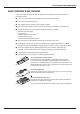
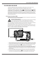
LST700 SERIES FIRE ALARM PANEL THE FIRE PANEL ENCLOSURE The panel is supplied with a plastic detachable lid, a plastic back box and a minimum of two separate PCBs. The relative location of these PCBs is indicated in Figure 1 below. The panel can be surface or semi-flush mounted. It must be sited internally in an area not subject to conditions likely to affect its performance, e.g. damp, salt-air, water ingress, extremes of temperature, physical abuse, etc.
LST700 SERIES FIRE ALARM PANEL FIRST FIX All System wiring should be installed to meet AS1670.1 - 2004. Other national standards of installation should be used where applicable. Cable types and limitations Consult AS1670.1 - 2004 for detailed information on cables, wiring and other interconnections. Note that all signal cabling forming part of a fire alarm system must be red sheathed to avoid confusion with other services.
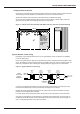
LST700 SERIES FIRE ALARM PANEL Fixing the base to the wall Using the five mounting holes provided (see figure 3 below), fix the base securely onto/into the wall. The mounting holes are suitable for use with No.8-10 or 4-5mm countersunk screws. Assess the condition and construction of the wall and use a suitable screw fixing. Any dust or swarf created during the fixing process must be kept out of the fire alarm panel and great care must be taken not to damage any wiring or components.
LST700 SERIES FIRE ALARM PANEL Sounder circuit wiring Four conventional sounder circuits are available on the fire alarm panel. These can accommodate up to 40 polarised sounders (at 20mA) or 32 bells (at 25mA) per system. If a full complement of sounders or bells are to be used, they should be split as equally as possible across all four sounder circuits.
LST700 SERIES FIRE ALARM PANEL Auxiliary input wiring Two non-latching auxiliary input connections are available to allow external control of sounders:Alert Input (ALERT): Operates the sounders intermittently when connected to 0V. Class Change Input (CC): Operates the sounders continuously when connected to 0V. If either of the above are triggered, they WILL NOT operate the panel’s remote or auxiliary fire outputs.
LST700 SERIES FIRE ALARM PANEL SECOND FIX Connecting the panel Connecting the panel’s internal connections and PCBs is best undertaken immediately prior to commissioning. Before you begin, we recommend you check all devices on the detector and sounder circuits are correctly connected (see pages 7 and 8) and that cable integrity is verified throughout the installation. Important: DO NOT use a high voltage insulation tester with any electronic devices connected.
LST700 SERIES FIRE ALARM PANEL Figure 9 : Power Supply PCB layout and mains connection details Incoming Mains cable must be segregated from other cables and should only enter the Panel through either of these knock-outs. Good quality cable glands must always be fitted. L N L N CONN1 PRIMARY FUSE F1 L = Live; N = Neutral, FUSE The incoming mains earth wire must be connected to the terminal marked and not to the base earth post. (The PSU earth strap connects the PCB to the base earth post).
LST700 SERIES FIRE ALARM PANEL Installing the Main Control PCB The panel’s Main Control PCB provides all the connections for the system’s detector circuits, sounder circuits, auxiliary inputs and auxilary outputs. It also provides the engineer with access to a wide range of engineering functions, details of which appear later in this manual.
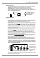
LST700 SERIES FIRE ALARM PANEL Connecting the detector and sounder circuits Incoming detector and sounder circuits should be connected to the relevant connector block on the Main Control PCB as shown in Figure 12 below. For typical detector and sounder circuit wiring diagrams, please refer to pages 7 and 8.
LST700 SERIES FIRE ALARM PANEL PROGRAMMING THE PANEL An overview of the panel’s controls Three control levels are available on the panel - general user (access level one), authorised user (access level two) and engineer (access level three), as detailed below: General user controls (access level one) When the panel is in its normal state, the indicator lights on the front of the enclosure give a comprehensive overview of the system’s current status.
LST700 SERIES FIRE ALARM PANEL From an installation point of view, detectors on zones assigned for coincidence should be installed in close proximity to each other. This ensures if the user is not around to investigate the cause of the alarm, that a detector in alarm on one zone is quickly confirmed by its neighbour on the corresponding zone in the event of a real fire. Alarms raised in zones not set up for coincidence will be processed as normal.
LST700 SERIES FIRE ALARM PANEL Accessing the engineer controls Before programming the panel, please refer to pages 14 and 15 for an overview of the various engineering functions available and the effect their implementation will have on the way the system operates. To gain access to the panel’s engineer functions, remove the panel lid using the Torx key provided and press the ACCESS LEVEL THREE FUNCTIONS button on the Main Control PCB (see Figure 13 below).
LST700 SERIES FIRE ALARM PANEL 5. Repeat steps 3 and 4 until the process is complete. To finish the function, press the ESCAPE ACCESS button or move onto the next programming function (Non-latching Zones) by pressing the ACCESS LEVEL THREE FUNCTIONS button. To program non latching zones 1. Press the ACCESS LEVEL THREE FUNCTIONS button until the NONLATCHING light flashes (any zones that are already programmed for non latching operation will now have their zone fault lights lit steady). 2.
LST700 SERIES FIRE ALARM PANEL FAULT DIAGNOSIS When a fault occurs on a critical part of the fire alarm system, the panel responds by activating its internal sounder and illuminating the general fault light and any other fault light(s) relating to the fault. The panel’s fault output will also activate (provided it has not been disabled). The type of faults typically indicated at the fire alarm panel are highlighted below.
LST700 SERIES FIRE ALARM PANEL 1.1 Zone Faults ■ To find out if an open circuit or head out fault has occurred on a detector zone:1. Remove the Panel’s lid using the torx key provided and press the ACCESS LEVEL THREE FUNCTIONS button on the Main Control PCB to gain access to the panel’s engineer functions (see below) SYSTEM FAULT REPEATER FAULT OPEN SHORT CIRCUIT CIRCUIT SW8 ACCESS LEVEL THREE FUNCTIONS COINCIDENCE DELAYS TEST NONLATCHING 2.
LST700 SERIES FIRE ALARM PANEL ■ The primary mains fuse (F1) is ruptured. Symptoms: the panel runs on batteries, but not on mains. The red hazardous voltages present light on the Power Supply PCB is off. Suggested action: (a) Isolate the mains supply, remove the Main Control PCB and check the PSU’s primary mains fuse (F1) for continuity. (b) If the fuse is ruptured it will be due to an excessive mains surge or a PSU fault. Check the components on the PSU for damage.
LST700 SERIES FIRE ALARM PANEL 1.3 System Faults System faults are unique in that they do not automatically clear when rectified. A total of three different types of system fault can occur - watchdog fault, site memory corruption fault or PLL (phase lock loop) fault. ■ To find out which type of system fault has occurred:1. Remove the Panel’s lid using the torx key provided and press the ACCESS LEVEL THREE FUNCTIONS button on the Main Control PCB to gain access to the panel’s engineer functions (see below).
LST700 SERIES FIRE ALARM PANEL 1.4 Repeater faults ■ To find out which of the repeater panels are faulty:1. Remove the panel’s lid using the torx key provided and press the ACCESS LEVEL THREE FUNCTIONS button on the Main Control PCB to gain access to the panel’s engineer functions (see below). SYSTEM FAULT REPEATER FAULT OPEN SHORT CIRCUIT CIRCUIT SW8 ACCESS LEVEL THREE FUNCTIONS COINCIDENCE DELAYS TEST NONLATCHING 2.
LST700 SERIES FIRE ALARM PANEL APPENDIX Stand-by battery calculation guide The standby time of the fire alarm panel after the mains has failed depends on the quiescent loading of the panel, the alarm load of the panel, and the capacity of the batteries. To determine the capacity of batteries required for any given stand-by period, the following formula should be used:- Standby Time in Ahr = 1.25 x ((TxA) + H x (P+Z)) The multiplier 1.
LST700 SERIES FIRE ALARM PANEL LST700 SERIES CONVENTIONAL FIRE ALARM PANEL technical specifications POWER SUPPLY SPECIFICATION Mains supply voltage Mains rated current Internal power supply Total output current limited to Supply and battery charger monitored for failure Batteries monitored for disconnection & failure Batteries protected against deep discharge Max.