LST700 SERIES FIRE ALARM PANEL LST700 SERIES FIRE ALARM CONTROL PANEL user manual & log book approved document no. DFU7001003 rev 4 LST700 SERIES USER MANUAL • Approved Document No.
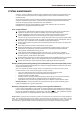
LST700 SERIES FIRE ALARM PANEL CONTENTS Safety ........................................................................................................................................ 3 Important information regarding the safe use of this fire alarm panel Fire Alarm Systems - An Overview ....................................................................................... 4 How fire alarm systems operate and a general overview of their key features System Maintenance ...................................
LST700 SERIES FIRE ALARM PANEL SAFETY The fire alarm panel is safe to operate provided it has been installed in compliance with the manufacturers instructions and used in accordance with this manual. Do not operate the fire alarm panel with its enclosure open. There is no need to open the enclosure except to carry out commissioning, maintenance and remedial work.
LST700 SERIES FIRE ALARM PANEL FIRE ALARM SYSTEMS - AN OVERVIEW The primary purpose of a fire alarm system is to provide early warning of a fire so that building occupants can be evacuated and action taken to stop the fire as soon as possible - all according to a predetermined plan. Alarms may be raised automatically, by smoke or heat detectors, or manually by a person operating a manual call point.
LST700 SERIES FIRE ALARM PANEL SYSTEM MAINTENANCE AS1670.1 - 2004 Fire Detection Systems design, installation and commissioning and AS18551.8 set out criteria to ensure that systems are correctly placed into service and then maintained in a fully operational state. At the end of this manual we have included an Installer ’s Statement and Commissioning Report which should be completed for each system.
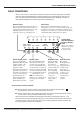
LST700 SERIES FIRE ALARM PANEL PANEL LAYOUT / ACCESSING THE CONTROLS 1 2 3 Silence Inter nal sounder Silence/Activate sounders 4 5 8 Fire Zones 2 3 4 5 6 7 8 1 2 3 4 5 6 7 8 fault output status remote output status Zone fault/disabled/test supply remote present output I 7 1 Contr ol Panel Reset Enable/ Disable 6 test accessed general disablement O Lamp test general power system repeater supply fault fault fault fault sounder auxiliary output status output delays statu
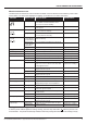
LST700 SERIES FIRE ALARM PANEL What the Indicators mean The table below summarises the various indicators available on the Fire Alarm Panel and what they mean in their various States. The final column highlights the page(s) you should turn to for further information.
LST700 SERIES FIRE ALARM PANEL FIRE CONDITIONS General Fire Light Fire Zone Lights Fire Zones 1 2 3 4 5 6 7 8 When the fire alarm panel receives an alarm trigger from a detector or manual call point located in a zone that is not already in a fire state, it will:■ Flash the general fire and appropriate fire zone light(s) on the front of its enclosure. ■ Sound its internal sounder.
LST700 SERIES FIRE ALARM PANEL FAULT CONDITIONS When a fault occurs on a critical part of the fire alarm system, the panel responds by activating its internal sounder and illuminating the general fault light and any other fault light(s) relating to the fault. The panel’s fault output will also activate (provided it hasn’t been disabled).
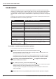
LST700 SERIES FIRE ALARM PANEL DISABLEMENTS Certain fire alarm panel functions can be temporarily disabled (i.e. switched off) to suit prevailing conditions. For example, if there is a risk of a false alarm in a zone, say from vehicle exhaust smoke in a loading bay, it is possible for the user to disable that zone during the risk period and enable it again afterwards. Another example is the disablement of outputs during a routine test or temporary fault.
LST700 SERIES FIRE ALARM PANEL The disablement/enablement process is complete when all available options have been selected in turn and the Next Option button is pressed for the last time. At this point all disabled options will be lit steady and all enabled options will have their lights switched off.
LST700 SERIES FIRE ALARM PANEL NOTES ON DELAYS What is a delay? A delay can be programmed into the fire alarm panel to postpone the activation of the alarm sounders and other outputs for a predetermined length of time. The delay period gives a responsible person time to investigate the cause of an alarm, usually in areas which are prone to false alarm (such as waiting rooms filled with smoke) before the building is evacuated.
LST700 SERIES FIRE ALARM PANEL SYSTEM SET-UP DATA CHART Important: This page should be carefully completed by an authorised engineer prior to system hand-over.
LST700 SERIES FIRE ALARM PANEL FIRE ALARM LOG BOOK It is recommended that a log book be kept on all sites and that it be maintained by a responsible person, who should ensure that all entries are properly recorded. This is necessary to satisfy the requirements of AS1670.1 and noncompliance may be an offence. It is also essential to record all maintenance and testing in accordance with the provisions of AS1851.8.
LST700 SERIES FIRE ALARM PANEL Details of tests (including fire drills), actual fire alarms, disablements or enablements and faults should be recorded here. False alarms and maintenance work should be recorded on page 18. DATE TIME EVENT e.g. test, fire alarm signal, fault ZONE DEVICE LST700 SERIES USER MANUAL • Approved Document No.
LST700 SERIES FIRE ALARM PANEL DATE 16 TIME EVENT e.g. test, fire alarm signal, fault ZONE DEVICE ACTION REQUIRED COMPLETED INITIALS LST700 SERIES USER MANUAL • Approved Document No.
LST700 SERIES FIRE ALARM PANEL DATE TIME EVENT e.g. test, fire alarm signal, fault ZONE DEVICE LST700 SERIES USER MANUAL • Approved Document No.
LST700 SERIES FIRE ALARM PANEL False alarms DATE TIME ZONE DEVICE THAT TRIGGERED THE ALARM SIGNAL CAUSE (IF KNOWN) BRIEF CIRCUMSTANCES (WHERE CAUSE IS UNKNOWN, RECORD ACTIVITIES IN THE AREA) MAINTENANCE VISIT REQUIRED? (YES OR NO) FINDINGS OF MAINTENANCE TECHNICIAN CATEGORY OF FALSE ALARM FURTHER ACTION REQUIRED DONE PLEASE TICK Maintenance work DATE 18 TIME ZONE DEVICE (WHERE APPLICABLE) (WHERE APPLICABLE) REASONS FOR WORK WORK CARRIED OUT FURTHER WORK REQUIRED SIGNATURE LST700 SERIES
LST700 SERIES FIRE ALARM PANEL Certificate of INSTALLATION for the fire alarm system at: 1. Name of premises ..................................................................................................................................... 2. Situated at ................................................................................................................................................. ........................................................................................................
LST700 SERIES FIRE ALARM PANEL CONTINUED FROM PREVIOUS PAGE Zone of Protection Alarm zone Number and type of actuating devices Number of actuating devices per zone* Heat A B C Fire D E Smoke Flame CO IR UV Manual Call Point Other Zone 1 Zone 2 Zone 3 Zone 4 Zone 5 Zone 6 Zone 7 Zone 8 Total number * Indicate with a number in brackets the number of actuating devices in concealed spaces. Additional information ............................................................................