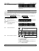
ADEMCO LYNXR-I Security Systems Programming Guide ARMED 1 2 RECORD VOLUME OFF ESCAPE 4 AWAY ADD STAY DELETE LIGHTS ON 7 K14116 3/06 Rev.
TABLE OF CONTENTS Data Fields ................................................................................................................................................................................. 3 ✻56 Enhanced Zone Programming ......................................................................................................................................... 11 ✻80 Device Programming ............................................................................................................
TO LOAD A DEFAULT SET: While in Program mode, press ✻97, then enter a number 1-4 corresponding to the default table desired. See the Installation Instructions for the default tables. Enter 0 if you are not selecting a default table. TO EXIT PROGRAMMING MODE: ✻98 Exits programming mode and prevents re-entry by: Installer Code + 8+ 0 + 0. If ✻98 is used to exit programming mode, system must be powered down, then press [✻] and [#] within 50 seconds of power up to re-enter programming mode.
Field Function Programmed Values ZONE SOUNDS AND TIMING (✱ 31– ✱ 39) ✱31 SINGLE ALARM SOUNDING/ZONE [ ] = Table 1 Default Values † [0] 1 = yes, limit once per arming period (also applies to long range radio output if “0” is selected in ✻91 field); 0 = no limit UL installations = 0 ✱32 FIRE SOUNDER TIMEOUT ✱33 ALARM BELL TIMEOUT † [0] 0=timeout; 1=no timeout † [1] 0 = none; 1=4 min; 2=8 min; 3=12 min; 4 = 16 min UL installations = 1 (4 min) minimum ✱34 EXIT DELAY † [70] | 00-99 = exit delay t
Field ✱42 Function Programmed Values [ ] = Table 1 Default Value SECONDARY PHONE NUMBER Enter up to 24 digits; Do not fill unused spaces. If fewer than 24 digits entered, pressing ✻advances to the next field. To clear entries from field, press ✻41✻. ! All four digits of the subscriber account number must be entered in Fields ✻43 and ✻44. If ten digit format is selected in ✻48 (option 5), all ten digits of the Subscriber Account number must be entered. For fields ✻43, ✻44: Enter 4 to 10 digits.
Field Function ✱49 SPLIT/DUAL REPORTING ** Pager Message A 7-digit code (plus optional 16-digit prefix) is sent to the pager consisting of a 3-digit event code, followed by 0 and a 3-digit user or zone number. See Installation Instructions for an explanation of the pager code, which takes the following form: AAAAAAAAAAAAAAAA-EEE-0NNN Programmed Values ✱50 15 SEC DIALER DELAY (BURG) ✱51 PERIODIC TEST REPORT ] = Table 1 Default Value [0] 0 = Disable (None, unless primary fails) TO PRIMARY PHONE No.
Field Function Programmed Values [ ] = Table 1 Default Value TO PROGRAM SYSTEM STATUS, & RESTORE REPORT CODES (✱59–✱76, & ✱89): With a 3+1 or 4+1 Standard Format: Enter a code in the first box: 1–9, 0, B, C, D, E, or F. Enter "#+10" for 0, "#+11" for B, "#+12" for C, "#+13" for D, "#+14" for E, "#+15" for F. A "0" (not "#+10") in the first box will disable a report. A "0" (not "#+10") in the second box will result in automatic advance to the next field when programming.
Field Function ✱75 RF XMTR LO BAT RST RPT CODE | [1,0] ✱76 TEST RESTORE RPT CODE | [0,0] | [0, 0] DYNAMIC SIGNALING FIELD ✻77 ✱77 DYNAMIC SIGNALING DELAY/ DYNAMIC SIGNALING PRIORITY Programmed Values[ ] = Table 1 Default Value 1st Entry (delay before switch CS reporting path) 0 = Redundant reporting 7 = 105 seconds on dialer and LRR/IP 8 = 120 seconds device 9 = 135 seconds 1 = 15 seconds #10 = 150 seconds 2 = 30 seconds #11 = 165 seconds 3 = 45 seconds #12 = 180 seconds 4 = 60 seconds #13 =
Field ✱90 Function Programmed Values[ EVENT LOGGING ] = Table 1 Default Value [3] 0 = None; 1 = Alarm/Alarm Restore; 2 = Trouble/Trouble Restore; 4 = Bypass/Bypass Restore; 8 = Open/Close. Example: To select “Alarm/Alarm Restore”, and “Open/Close”, enter 9 (1 + 8); To select all, enter #15. Note: System messages are logged when any non-zero selection is made.
Field Function Programmed Values ✱99 EXITS PROGRAMMING MODE (ALLOWS RE-ENTRY) Installer Code + 8 + 0 + 0 or: Power-up, then press "✻" and "#" within 50 seconds of power up or from exiting Programming mode. Note: [ ] = Table 1 Default Value After exiting Program mode, the system takes up to 1 minute to reset. To bypass the reset delay, press [#] + [0].
✻56 ENHANCED ZONE PROGRAMMING PROCEDURE Use this mode to program zone information. Press ✻56 while in programming mode. Notes: (1) Entering a number other than the one specified may give unpredictable results. (2) You may find it convenient to adjust the volume setting before entering the Programming Mode. This will allow you to clearly hear feedback announcements or system beeps. A 02 b zt C rc d i E l ZONE NUMBER Enter the 2-digit zone number to be programmed.
✻56 ENHANCED ZONE PROGRAMMING PROCEDURE DELETE ZONE PARAMETERS 0 = Discard the delete request. 1 = Confirm the requested delete. If 00 is entered in the zone type, confirmation of the delete request will delete all information associated with zone currently being programmed. F If 0 is entered in the loop number, confirmation of the delete request will delete the serial number associated with zone currently being programmed.
✻80 DEVICE PROGRAMMING Use this mode to program Powerline Carrier Devices or zone lists for Chime by Zone feature. Press ✻80 while in programming mode. Note: Entering a number other than the one specified may give unpredictable results. 80 A 0I b aa C et d zl E zt F zl IA zt Device Programming 0 = Exit mode, upon which this prompt blinks.
✻81 ZONE LISTS Use this mode to define zone lists for Powerline Carrier Devices and/or for the chime by zone feature. Press ✻81 while in programming mode. Note: Entering a number other than the one specified may give unpredictable results. 8I A 0I b zz C d E ZONE LIST PROGRAMMING 0 = Exit mode, upon which this prompt blinks. 1 = Enter mode ZONE LIST NUMBER Enter the 2-digit zone list number (01-03) to be programmed (use zone list 03 for chime by zone feature).
✻83 ENHANCED SEQUENTIAL MODE Use this mode to enter transmitter serial numbers. Press ✻83 while in programming mode. A 02 IA zz IA LC ZONE NUMBER Enter the 2-digit zone number of the first transmitter to have its serial number entered. The system will announce the Voice Descriptor for the selected zone if it has been programmed. [✻] = Continue; system searches for zones not yet entered, (for zones 2 to 25 a zone type must be entered) then advances to ENROLL SERIAL NUMBER prompt (1b).
✻84 ASSIGN ZONE VOICE DESCRIPTORS Use this mode to assign voice descriptors for each zone. These are the descriptors that are announced when the system announces any event involving a zone number. Press ✻84 while in programming mode. Note: Entering a number other than the one specified may give unpredictable results. ASSIGN ZONE VOICE DESCRIPTORS 0 = Exit mode, upon which this prompt blinks. 1 = Enter mode ZONE NUMBER zz Enter the 2-digit zone number (zz) for which this descriptor is being assigned.
✻85 RECORD CUSTOM VOICE DESCRIPTORS Use this mode to record up to 5 custom voice descriptors for use with zone announcements. Press ✻85 while in programming mode. NOTE: Entry of a number other than one specified will give unpredictable results. 85 A 7d RECORD CUSTOM VOICE DESCRIPTORS 0 = Exit mode, upon which this prompt blinks. 1 = Enter mode CUSTOM DESCRIPTOR NUMBER Enter 7 + d + [✻] where d = 0-4, each representing custom word 70, 71, 72, 73 or 74 respectively. Existing descriptor will be announced.
✻56 ENHANCED ZONE PROGRAMMING WORKSHEET Fill in the required data on this worksheet, then follow the programming procedure in the Installation and Setup Guide. ZONES ON CONTROL: See explanation of headings (defaults shown are for Table 1) Zone Description Zone No.
Zone No. (A 02) Zone Type (zt) Alarm Report Code in hex (rc) Input Type (i) Loop No.
POWERLINE CARRIER DEVICES WORKSHEET FOR ✻80, and ✻81. Applicable only if Powerline Carrier Devices are to be used, or chime-by-zone feature is used. UL Powerline Carrier Devices have not been evaluated by UL. ✱80 OUTPUT DEVICES Fill in the required data on the worksheet on below and follow the programming procedure in the Installation Instructions as you enter the data during the displays and prompts that appear in sequence. Note: Field ✱25 must be programmed with a House Code.
✻81 ZONE LISTS FOR OUTPUT DEVICES Fill in the required data on the worksheet below and follow the procedure in the installation manual as you enter the data during the displays and prompts that appear in sequence. Note: Record desired zone numbers below. More or fewer boxes than shown may be needed, since any list may include any or all of a system's zone numbers. Zone List 1: Started or stopped by zone numbers (enter 00 to end entries). .etc.
*WHEN AVAILABLE THIS DEVICE COMPLIES WITH PART 15 OF FCC RULES. OPERATION IS SUBJECT TO THE FOLLOWING TWO CONDITIONS: (1) THIS DEVICE MAY NOT CAUSE HARMFUL INTERFERENCE, AND (2) THIS DEVICE MUST ACCEPT ANY INTERFERENCE RECEIVED, INCLUDING INTERFERENCE THAT MAY CAUSE UNDESIRED OPERATION.
– Notes – -23-
165 Eileen Way, Syosset, New York 11791 ‡K14116*Š K14116 3/06 Rev. B Copyright © 2006 Honeywell International Inc. www.honeywell.