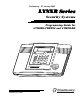
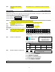
Preliminary - 27 January 2003 LYNXR Series Security Systems Programming Guide for LYNXR/LYNXR24 and LYNXR-EN ARMED 1 2 RECORD VOLUME OFF ESCAPE 4 AWAY ADD STAY DELETE LIGHTS ON 7 5 6 BYPASS STATUS Monitronics 9 CODE CHIME NO DELAY FUNCTION 0 AUX SELECT 3 PLAY TEST 8 LIGHTS OFF READY # R I N T E R N A T I O N A L , I N C . Monitronics K5965MTV1 (bx) 1/22/03 I N T E R N A T I O N A L , I N C .
TABLE OF CONTENTS Data Fields................................................................................................................................................................................. 3 *56 Enhanced Zone Programming........................................................................................................................................... 11 *80 Device Programming ............................................................................................................
TO LOAD A DEFAULT SET: While in Program mode, press ✱97, then enter a number 1-4 corresponding to the default table desired. See the Installation Instructions for the default tables. Enter 0 if you are not selecting a default table. NOTE: The telephone numbers in Fields ✱41 and ✱42 are not affected by defaults. TO EXIT PROGRAMMING MODE: ✱98 Exits programming mode and prevents re-entry by: Installer Code + 8+ 0 + 0.
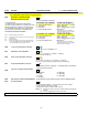
Field Function Programmed Values ZONE SOUNDS AND TIMING (✱ 31– ✱ 39) SINGLE ALARM SOUNDING/ZONE ✱31 [ ] = Table 1 Default Values † [0] 1 = yes, limit once per arming period (also applies to long range radio output if “0” is selected in *91 field); 0 = no limit UL installations = 0 ✱32 FIRE SOUNDER TIMEOUT ✱33 ALARM BELL TIMEOUT † [0] 0=timeout; 1=no timeout † [1] 0 = none; 1=4 min; 2=8 min; 3=12 min; 4 = 16 min UL installations = 1 (4 min) minimum ✱34 EXIT DELAY † [70] | 00-99 = exit delay t
✱42 Not Viewable. Press ✻ + Field Number to advance to next field. TWO WAY VOICE PHONE NUMBER Field Function Programmed Values [ ] = Table 1 Default Value For fields *43 , *44: Enter 0–9; #+11 for B; #+12 for C; #+13 for D; #+14 for E; [#+15 for F]. Enter ✱ as 4th digit, if 3+1 dialer reporting is to be used. If only 3 digits used, pressing ✱ advances to the next field. To clear entries from field, press ✱43✱ or ✱44✱ .Examples: For Acct. 1234, enter: 1 | 2 | 3 | 4 For Acct.
Field Function Programmed Values [ ] = Table 1 Default Value NOTES: (1) If pager is enabled (Options 6-9 in Field *49) the end user cannot use the “Follow me”, and “Follow me” reminder features. (2) LYNX reports system status as a voice message. ✱49 CENTRAL STATION/PAGER REPORTING/FOLLOW ME ** Pager Message A 7-digit code (plus optional 16-digit prefix) is sent to the pager consisting of a 3-digit event code, followed by 00 and a 2-digit user or zone number.
Field Function Programmed Values [ ] = Table 1 Default Value TO PROGRAM SYSTEM STATUS, & RESTORE REPORT CODES (✱59–✱76, & ✱89): With a 3+1 or 4+1 Standard Format: Enter a code in the first box: 1–9, 0, B, C, D, E, or F. Enter "#+10" for 0, "#+11" for B, "#+12" for C, "#+13" for D, "#+14" for E, "#+15" for F. A "0" (not "#+10") in the first box will disable a report. A "0" (not "#+10") in the second box will result in automatic advance to the next field when programming.
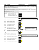
Field Function Programmed Values[ ✱75 RF XMTR LO BAT RST RPT CODE | [1,0] ✱76 TEST RESTORE RPT CODE | [0,0] ] = Table 1 Default Value OUTPUT AND SYSTEM SETUP (*80–*92) DEVICE PROGRAMMING MENU ✱80 MODE ZONE LISTS MENU MODE ✱81 ENHANCED SEQUENTIAL MODE ✱83 See procedure later in this manual. ✱84 ASSIGN ZONE VOICE DESCRIPTOR See procedure later in this manual. ✱85 RECORD CUSTOM VOICE DESCRIPTOR See procedure later in this manual.
Field ✱91 Function LYNXR/LYNXR24 LONG RANGE RADIO/ALARM AUDIO VERIFICATION (AAV)/REMOTE PHONE CONTROL Programmed Values[ ] = Table 1 Default Value [4] 0 = Long range radio only 1 = AAV and remote phone control 2 = Long range radio and remote phone control 4 = AAV only Notes: (1) If long range radio is being connected alarm audio verification cannot be used.
Field Function ✱95 RING DETECT COUNT FOR DOWNLOADING/REMOTE PHONE CONTROL MODE Programmed Values [ ] = Table 1 Default Value [15] 0 = Disable Station Initiated Download; 1–14 = number of rings (1–9, [#]+10 =10, [#] +11 =11, [#] +12 =12, [#] +13 =13, [#] +14 =14); 15 = answering machine defeat ([#] +15 =15) ✱96 INITIALIZE DOWNLOAD ID & SUBSCRIBER ACCOUNT No entry required ✱97 SET ALL PROGRAM FIELDS TO 1 OF 4 SETS OF DEFAULT VALUES Enter 1-4 to select from default tables 1-4 Enter 0 to abort.
*56 ENHANCED ZONE PROGRAMMING Use this mode to program zone information. Press *56 while in programming mode. Notes: (1) Entering a number other than the one specified may give unpredictable results. (2) You may find it convenient to adjust the volume setting before entering the Programming Mode. This will allow you to clearly hear feedback announcements or system beeps. A 0I b zt C rc d i E l ZONE NUMBER Enter the 2-digit zone number to be programmed. selected zone, if it is programmed.
DELETE ZONE PARAMETERS 0 = Discard the delete request. 1 = Confirm the requested delete. If 00 is entered in the zone type, confirmation of the delete request will delete all information associated with zone currently being programmed. F If 0 is entered in the loop number, confirmation of the delete request will delete the serial number associated with zone currently being programmed. Note: 00 was entered as a zone type in prompt (b), 00 will be retained and system will advance to prompt (1C).
*80 DEVICE PROGRAMMING Use this mode to program Powerline Carrier Devices or zone lists for Chime by Zone feature. Press *80 while in programming mode. Note: Entering a number other than the one specified may give unpredictable results. 80 A 0I b aa C et d zl E zt F zl IA zt Device Programming 0 = Exit mode, upon which this prompt blinks.
*81 ZONE LISTS Use this mode to define zone lists for Powerline Carrier Devices and/or for the chime by zone feature. Press *81 while in programming mode. Note: Entering a number other than the one specified may give unpredictable results. 8I A 0I b zz C d E ZONE LIST PROGRAMMING 0 = Exit mode, upon which this prompt blinks. 1 = Enter mode ZONE LIST NUMBER Enter the 2-digit zone list number (01-03) to be programmed (use zone list 03 for chime by zone feature).
*83 ENHANCED SEQUENTIAL MODE Use this mode to enter transmitter serial numbers. Press *83 while in programming mode. A 0I IA zz IA LC ZONE NUMBER Enter the 2-digit zone number of the first transmitter to have its serial number entered. The system will announce the Voice Descriptor for the selected zone if it has been programmed. [*] = Continue; system searches for zones not yet entered, (for zones 2 to 25 a zone type must be entered) then advances to ENROLL SERIAL NUMBER prompt (1b).
*84 ASSIGN ZONE VOICE DESCRIPTORS Use this mode to assign voice descriptors for each zone. These are the descriptors that are announced when the system announces any event involving a zone number. Press *84 while in programming mode. Note: Entering a number other than the one specified may give unpredictable results. 84 A zz b vv C vv d vv ASSIGN ZONE VOICE DESCRIPTORS 0 = Exit mode, upon which this prompt blinks.
*85 RECORD CUSTOM VOICE DESCRIPTORS Use this mode to record up to 5 custom voice descriptors for use with zone announcements. Press *85 while in programming mode. NOTE: Entry of a number other than one specified will give unpredictable results. RECORD CUSTOM VOICE DESCRIPTORS 0 = Exit mode, upon which this prompt blinks. 1 = Enter mode 85 A CUSTOM DESCRIPTOR NUMBER Enter 7 + d, where d = 0-4, each representing custom word 70, 71, 72, 73 or 74 respectively. Existing descriptor will be announced.
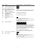
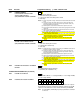
Zone No. Zone (A 01) Type (zt) Alarm Report Code in hex (rc) Input Type (I) Loop No.
POWERLINE CARRIER DEVICES WORKSHEET FOR *80, and *81. Applicable only if Powerline Carrier Devices are to be used, or chime-by-zone feature is used. UL 80 ✱ Powerline Carrier Devices are not UL Listed for fire or burglary functions and are intended for home automation. OUTPUT DEVICES Fill in the required data on the worksheet on below and follow the programming procedure in the Installation Instructions as you enter the data during the displays and prompts that appear in sequence.
81 ZONE LISTS FOR OUTPUT DEVICES ✱ Fill in the required data on the worksheet below and follow the procedure in the installation manual as you enter the data during the displays and prompts that appear in sequence. Note: Record desired zone numbers below. More or fewer boxes than shown may be needed, since any list may include any or all of a system's zone numbers. Zone List 1: Started or stopped by zone numbers (enter 00 to end entries). .etc.
MONITRONICS LYNXR-EN PROGRAMMED VALUES The following table summarizes the values have been programmed into the Monitronics LYNXR-EN at the factory and replace the Table 1 values that are shown in the Installation Guide. Loading any other default table will override these programmed values.
*80 OUTPUT DEVICES Start Device Number Action Event Zone List Stop Zone Type System Operation 8 2 Note: Device numbers 1-7 have no default values 33 *81 ZONE LISTS FOR OUTPUT DEVICES Zone List Zone List 1 Zone List 2 Zone List 3 Zone No.
-23- INCOMING PHONE LINE 8 POSITION JACK LOCAL SOUNDER DISABLE SHUNT REMOVE TO DISABLE TO HANDSET PHONE LINE RJ11 THE LYNX SERIES CONTROLS ARE EQUIPPED WITH AN INTEGRAL RECHARGEABLE BATTERY PACK. LYNXR: P/N LYNXRCHKIT-SC LYNXR24: P/N LYNXRCHKIT-HC LYNXR-EN: P/N LYNXRCHKIT-SC OR P/N LYNXRCHKIT-HC REPLACE EVERY FOUR YEARS THIS DEVICE COMPLIES WITH PART 15 OF FCC RULES.
Monitronics I N T E R N A T I O N A L , I N C .