ADEMCO VISTA-12A Security Systems Programming Guide K10022-1PR 9/04 Rev.
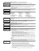
TO START PROGRAM MODE, use method A or B (must use alpha keypad connected to keypad terminals): A. POWER UP, then press both [∗] and [#] at same time within 50 seconds of powering up. (if ∗98 was used to exit program mode, this is the only method that can be used to start program mode again) B. Initially, key: Installer Code (4 + 1 + 1 + 2) plus 8 + 0 + 0. Data Field Programming Procedures Task Procedure Go to a Data Field Entering Data Press [∗] + [Field Number], followed by the required entry.
PR O GR A MM I N G F O R M Entry of a number other than one specified will give unpredictable results. Default values are shown in brackets, with unique table 1 and table 2 values indicated where applicable (DT1 = default table 1; DT2 = default table 2); see page 20 for a complete list of factory default tables 1 and 2.
∗49 Split/Dual Reporting ∗69 [0] 0 = Disable (standard/backup reporting only) Primary Phone No. Second Phone No. 1 = Alarms, Restore, Cancel Others 2 = All except Open/Close, Test Open/Close, Test 3 = Alarms, Restore, Cancel All 4 = All except Open/Close, Test All 5 = All All ∗50 ∗70 Alarm Restore Rpt Code ∗71 Trouble Restore Rpt Code ∗72 Bypass Rest. Rpt Code ∗73 | Secondary Subscriber ID # (Common Part.) Dialer Delay (Burg) [0] Primary Subscriber ID # (Common Part.
∗92 Telecom Monitor Enable ∗176 Siren Options [0,0] Entry 1: 0 = disabled 1 2 1-15 = enabled, after 1 15 min. line outage (#+10 = 10 min; #+11 = 11 min; #+12 = 12 min; #+13 = 13 min; #+14 = 14 min; #+15 = 15 min) Entry 2: 0 = keypad display when line is faulted 1 = keypad display plus keypad trouble sound 2 = Same as “1”, plus programmed output device STARTS. If any partition is armed, external sounder also activates.
∗187 Sounder Mimic on Trigger 1 KEYPAD OPTIONS [0] NOTES: 1. Keypad 1 (addr 16) options are factory set and cannot be changed. 2. Each keypad must be assigned a unique address. Keypads programmed with the same address will give unpredictable results.
*56 ZONE PROGRAMMING WORKSHEET [default values shown in brackets] Zone Zn Type Partition 1 2 3 4 5 6 [01] [04] [03] [03] [03] [03] Report [1] [1] [1] [1] [1] [1] Zone Zn Type Partition 9 10 11 12 13 14 15 16 17 18 19 20 21 22 23 24 [1] 49 [1] 50 [1] 51 [1] 52 [1] 53 [1] 54 [1] 55 [1] 56 [1] 57 [1] 58 [1] 59 [1] 60 [1] 61 [1] 62 [1] 63 [1] 64 [05] N/A 91 N/A N/A 92 [00] 95 [00] 96 [07] 99 [yes] [yes] [yes] [yes] [yes] [yes] Report [yes] [yes] [yes] [yes] [yes] [yes] [yes] [yes] [yes] [yes] [yes] [yes]
∗56 ZONE PROGRAMMING MENU MODE (press *56 while in Program mode) SET TO CONFIRM? 0 = NO 1 = YES 0 = no 1 = yes (prompt appears after entering the serial and loop numbers to confirm each transmitter) We recommend that you confirm the programming of every transmitter. Enter Zn Num. (00 = Quit) Enter the zone number being programmed: wired zones 01-6 and 10-14 for zone doubling; expansion zones 17-24; wireless zones 09-24; RF button zones 49-64 91 = addr.
10 INPUT S/N L A022-4064 1 XMIT TO CONFIRM PRESS ✱ TO SKIP Entd A022-4063 1 Rcvd A022-4064 1 Zn ZT RC 10 03 10 In: L RF: 1s PROGRAM ALPHA? 0 = NO 1 = YES 0 ENTER ZN NUM. (00 = QUIT) 11 If the serial/loop number combination is not a duplicate in the system, a display showing the serial number and loop number entry appears. [∗] to continue This prompt will only appear if you answered “Yes” at the first prompt in this section.
Wireless Key Programming Templates (press the [D] key from *58 Menu mode Summary Screen display) This procedure programs the wireless keys, but a key is not active until it is assigned to a user number (see System Operation section, assigning attributes command in the Installation Instructions). Enter desired template number 1–6 (see chart below). Press [#] if you want to return to *58 Menu mode Summary Screen. If necessary, press [#] to back up and re-enter template number.
Table of Device Addresses Address Report† Device 00 01 02 03 017-23 100 101 102 103 117-123 08 13 16 17 18 19 20 21 22 23 28 Programmed by… RF Receiver *56 zone programming: input device type entry; AUI Device 1 Automatic if AUI enable field *189 enabled for AUI 1 AUI Device 2 Automatic if AUI enable field *189 enabled for AUI 2 Alternative Communication Media (ACM) automatic if ECP Contact ID Output for ACM field *29 enabled Telecommand Voice Module same as keypad enables; see below Zone Expanders (4
OUTPUT RELAYS/POWERLINE CARRIER DEVICES WORKSHEET FOR ∗79, ∗80 and ∗81. For keypad activated devices, use *79 Menu mode to assign a system output number and associate its corresponding device. For automatic activation, use *79 Menu mode as above, and use *80 Menu mode to define the system condition that will activate/deactivate the device(s). ∗79 RELAY/POWERLINE CARRIER DEVICE MAPPING (Must program before using *80) OUTPUT TYPE Relay X10 Output Module Pos Unit Description No. Addr. (1-4) No.
✱80 OUTPUT DEFINITIONS NOTES: 1. For Relays, 4229, 4204 and 6164 devices are programmed in *79, *80, and *81 modes. 2. For Powerline Carrier devices (plcd), field ✱27 must be programmed with a House Code. 3. Tampers of expansion units cannot be used to operate devices.
Start Output Definition mode by pressing ∗80 while in Data Programming mode. Enter the output function number to be defined Output Funct. # 01-12 = output function number [∗] to continue (00 = Quit) 01 00 = exit 01 A E P Trig ?00 0 0 – ZL=1 This screen displays a summary of the current output programming A = Output Action; E = Triggering event; P = Partition; Trig = Trigger type Question mark indicates the device shown has not been mapped. Use *79 Menu mode to map the device.
✱81 ZONE LISTS List No. 01 02 03 04 05 06 07 08 09 10 11 12 Used For… Contains These Zones… General Purpose (GP) General Purpose Chime-by-Zone or GP Linked Zones Night-Stay Zones or GP General Purpose General Purpose Final Contact Set Zones or G P Zones activating pager 1 or G P Zones activating pager 2 or G P General Purpose Exit Zones (*88) or GP NOTES: • Any list may include any or all of the system's zone numbers. • A zone list can be assigned to more than one output relay.
*82 DESCRIPTOR PROGRAMMING Start Zone Descriptor Programming mode by pressing *82 while in Data Programming mode. Program Alpha ? 0=No, 1=Yes 00 The “Program Alpha ?” prompt appears. 1 = program zone descriptors or partition descriptors 0 = exit [∗] to continue This prompt selects whether you are entering zone descriptors or entering partition descriptors.
*83 CONFIGURABLE ZONE TYPE PROGRAMMING CONFIGURABLE ZONE TYPE WORKSHEET Option Zone Attributes Bypass Option Response to Short Response to Open Vent Zone Zone Processing Sound on Trouble Sound on Alarm Dial Delay Display Options Contact ID Code ZT 90 ZT 91 ZT 92 ZT 93 Option Selections Zone Attributes 0 = none 1 = exit delay only 2 = entry/exit 1 3 = entry/exit 2 4 = follows entry/exit 5 = has verification† 6 = resettable Bypass Options 0 = cannot be bypassed 1 = auto bypassed when armed STAY Respons
Schedules (installer code + [#] + [6] [4]; Sched No. Event Device No.
DEVICE NUMBER XX X This prompt appears if event “2” (user access) was selected. Otherwise it is skipped. 1-8 = group number [∗] to continue to the “Start” prompt. X This prompt appears if events “3-7, or 10” were selected. Otherwise it is skipped.
– VISTA-12A DEFAULT TABLES – Field 20 21 22 23 24 25 26 27 29 31 32 33 34 35 36 37 38 39 40 41 42 43 44 45 46 47 48 49 50 51 52 53 54 55 59 60 61 62 63 64 65 66 67 68 69 70 71 72 73 74 75 76 77 78 84 85 86 87 88 89 90 91 92 93 94 95 Installer code Quick arm enable RF options Quick {forced} bypassed RF house ID Arming prevention override Chime by zone X10 ECP for ACM not used in Australia Single alarm sounding per zone fire sounder time out Siren time out Exit delay Entry delay 1 Entry delay 2 Audible Exit
– VISTA-12A DEFAULT TABLES (continued)– Field 160 161 162 163 164 165 166 173 175 176 177 178 180 181 182 183 185 186 187 188 189 190 191 192 193 194 195 196 197 198 199 Pager 1 phone number Pager 1 characters Pager 1 reporting options Pager 1 phone number Pager 1 characters Pager 1 reporting options pager delay options for alarms RF reporting options Tamper options Siren options Device Duration 1 , 2 RF supervision and RF Jam option Zone bypass limits AC and Clock display options Summer time switchover Da
WARNING THE LIMITATIONS OF THIS ALARM SYSTEM While this System is an advanced design security system, it does not offer guaranteed protection against burglary, fire or other emergency. Any alarm system, whether commercial or residential, is subject to compromise or failure to warn for a variety of reasons. For example: • Intruders may gain access through unprotected openings or have the technical sophistication to bypass an alarm sensor or disconnect an alarm warning device. • Intrusion detectors (e.g.
LIMITED WARRANTY Honeywell International Inc.
www.honeywell.com/security N219 2 + 3 165 Eileen Way, Syosset, NY 11791 Copyright © 2004 Honeywell International Inc. ALL OUTPUTS ARE POWER LIMITED. 4 + NOTE: KEYPAD (S) CURRENT (IN ALL PARTITIONS) AND ALL OTHER DEVICES DRAWING POWER FROM TERMS 4 & 5 MUST BE INCLUDED IN AUX CURRENT DRAIN CALCULATIONS. USE TRIGGER MODULE AUX POWER TERMINALS FOR SUPERVISED AUX POWER CONNECTION AUX. POWER OUTPUT 10.5-13.