
Setup guide


Index
Index-2
Limited Warranty ...........................................................B-2
Local Tests.................................................................. 11-1
Lock............................................................................... 2-1
Long-Range Radio ............................................... 1-2, 2-11
Loop ............................................................................. 5–1
Low Bat Message........................................................ 11-2
LRR ............................................................................. 2-11
LRR communication Failure ........................................ 11-3
Mechanics of Programming........................................... 3-3
Mounting Cabinet .......................................................... 2-1
Mounting Lock............................................................... 2-1
Mounting the 5800TM Module....................................... 2-8
Mounting the Control Circuit Board ............................... 2-1
Mounting the Control with RF Receiver......................... 2-2
Mounting the Keypads................................................... 2-3
NFPA Requirements ..................................................... 2-6
No Alarm Response ...................................................... 3-2
Optima 24 Plus FAX96 Modem................................... 12-1
Other Displays............................................................. 11-3
Output Device Programming-
∗
80.................................. 6–1
Output Relays................................................................ 1-1
Output To Long Range Radio........................................ 4-2
PABX Access Code....................................................... 4-2
Paging Feature....................................................... 1-1, 4-3
Panic Keys .................................................................. 10-2
Perimeter Burglary ........................................................ 3-1
Phone Module Access Code ......................................... 4-1
Phone Module problems.............................................. 2-10
Power Problems.......................................................... 11-2
Programming Overview................................................. 3-1
Programming Relays..................................................... 4-7
Programming Zone Descriptors..................................... 8-1
Quick-Arm Feature........................................................ 1-1
Receiver Supervision .................................................... 2-7
Receiver's DIP switch setting ........................................ 2-7
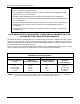
Regulatory Agency Statements.....................................A-1
Relay Programming Example....................................... 6–4
Relay-ACTION ............................................................. 6–1
Relay-START ............................................................... 6–1
Relay-STOP ................................................................. 6–2
Remote Keypads........................................................... 1-1
Remote Programming and Control (Downloading)...... 12-1
Report Code Formats.................................................... 9-1
Restore Report Codes (
∗
70 –
∗
75) ................................ 4-6
RF Interference ............................................................. 2-7
RF Jam Detection.......................................................... 1-1
RF Receiver .................................................................. 2-7
RJ31X Jack ................................................................. 2-10
Security Codes..................................................... 1-1, 10-1
Sounder (Bell) Connections .......................................... 2-4
Specifications and Accessories................................... 13-1
Split/Dual Reporting ...................................................... 4-3
Summary of Arming Modes......................................... 10-1
Supervised Fire ............................................................. 3-2
Supervised RF .............................................................. 2-9
Supplementary Power................................................... 2-3
System Communication ................................................ 9-1
System Operation........................................................ 10-1
System Setup Fields
∗
20 –
∗
27) .................................... 4-1
System status and report codes.................................... 4-4
System Status and Report Codes (
∗
60-
∗
68,
∗
70-
∗
75).. 4-4
Table of Contact ID Event Codes.............................. 9-3, 3
Tamper Protection......................................................... 2-8
Telco Line.................................................................... 2-10
Test Mode ................................................................... 11-1
Testing the System...................................................... 11-1
Transmitter Battery Life................................................. 2-8
Transmitter Input Types ................................................ 2-9
Transmitter Loop Identification......................................5–3
Transmitter Serial Number Removal .............................5–7
Transmitter Sniffer Mode...................................... 2-9, 11-1
Transmitter Supervision ................................................ 2-8
Trouble by Day/Alarm by Night ..................................... 3-2
Trouble condition......................................................... 11-2
Trouble Conditions ...................................................... 11-2
Troubleshooting Guide................................................ 11-3
UL Notices..................................................................... A-2
Unsupervised Button..................................................... 2-9
Unsupervised RF........................................................... 2-8
VIP Module........................................................... 1-1, 10-2
Warning Symbol...............................................................vi
Wireless Expansion....................................................... 1-1
Wireless Key Templates........................................5–8, 5–9
Wiring Run Chart........................................................... 2-3
Wiring the 5800TM Module ........................................... 2-8
Wiring the AC Transformer............................................ 2-4
Word String ................................................................... 8-3
Xmtr Serial Number labels ....................................5–3, 5–6
Zone Descriptors.................................................... 1-2, 8-4
Zone List Displays.........................................................7–1
Zone Lists......................................................................7–1
Zone Programming –
∗
56..............................................5–1
Zone Programming –
∗
58..............................................5–5
Zone Removal...............................................................5–6
Zone Response Type Definitions .................................. 3-1
Zone Sounds and Timing (
∗
28 –
∗
39)............................ 4-2
Zone Type Choices .......................................................6–3