
Troubleshooting guide
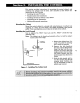
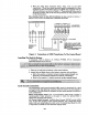
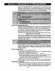

3. Connect remote Keypads for Partition 1 to terminals 4, 5,6, and 7 on the
control board, as shown in Figure 5.
4. Connect remote Keypads for Partition 2 to the 4-pin connector on the
control board (see the Summary of Connections diagram for location of
the 4-pin connector for partition 2).
KEYPADCONNECTOR CABLE(SUPPLIED WITH VISTA-20HW)
o
5
0
GREEN
PARTITION1 KEYPADS
6
0
YELLOW
7
CONTROL
TERMINALS
PARTITION 2 KEYPADS
CONNECTOR PINS FOR
PARTITION2 ON CONTROLBOARD
Figure 5. Keypad Connections To The Control Board
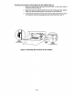
Mounting the Keypade
1. Make sure addressable type keypads (4137AD, 5137AD, 6128, 6137,
6138, and 6139) are set to non-addressable mode (address 31), which is
the factory default setting. Refer to the instructions provided with the
keypad for address setting procedure.
2. Mount the keypads at a height that is convenient for the user. Refer to
the instructions provided with the keypad for mounting procedure.
You can either surface mount or flush mount keypads (using an
appropriate Trim Ring Kit: 5137TRK or 6139 TRK). Refer to the
mounting instructions and template included with the keypad and/or
trim ring kit for specific information.
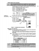
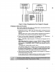
Using a Supplementary Power Supply to Power Additional Keypade
The control provides 600mA for powering keypads (up to a maximum of 4 per
partition) and other devices from the auxiliary power output. The backup
battery will supply power to these keypads in the event that AC power is lost.
When the control’s auxiliary power load for all devices exceeds 600 mA, you
can power additional keypads from a regulated, 12VDC power supply (e.g.,
487–12 supplies 12V, 250A, 488–12 supplies 12V, 500mA). Use a UL
Listed, battery-backed supply for UL installations.
The 487–12/488-12 power supplies have a backup battery which can power
these keypads in the event of AC power loss.
colors shown. Be sure to observe the current ratings for the power supply
used.
-17-