VISTA-128FBP VISTA-250FBP Commercial Fire and Burglary Partitioned Security System with Scheduling Installation and Setup Guide K0376V2 7/09 Rev.
Table of Contents • • • • • • • • • • • • • • • • • • • • • • • • • • • • • • • • • • • • • • • • • • • • • • • • • Commercial Fire and Burglary........................................................................................................... i General Requirements ...................................................................................................................................... ix Programming Field Settings for UL864 Compliance...................................................
Table of Contents Zone Response Type Definitions.....................................................................................................................4-6 Zone Input Type Definitions...........................................................................................................................4-8 Programming for Communicator ...................................................................................................................4-9 Programming for the Event Log............
Table of Contents UL Installation Requirements....................................................................................................................... A-1 UL864/NFPA Local Fire ................................................................................................................................ A-1 UL864/NFPA Central Station and Remote Station Fire .............................................................................
List of Figures • • • • • • • • • • • • • • • • • • • • • • • • • • • • • • • • • • • • • • • • • • • • • • • • • Figure 1-1: Isolating Fire Devices from Burglary Devices.....................................................................................................1-4 Figure 3-1: Installing the Lock...............................................................................................................................................3-1 Figure 3-2: Cabinet Attack Resistance Considerations ......
Conventions Used in This Manual • • • • • • • • • • • • • • • • • • • • • • • • • • • • • • • • • • • • • • • • • • • • • • • • • Before you begin using this manual, it is important that you understand the meaning of the following symbols (icons). UL These notes include specific information that must be followed if you are installing this system for a UL Listed application.
viii
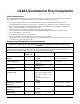
UL864 (Commercial Fire) Compliance • • • • • • • • • • • • • • • • • • • • • • • • • • • • • • • • • • • • • • • • • • • • • • • • • General Requirements The VISTA-128FBP/VISTA250FBP control panels provide features that allow the system to meet UL864 Commercial Fire requirements. To meet these requirements, follow the guidelines outlined in this section. • • • • • • • • • The reporting of bypassed points to the central station must be enabled in Report Code Programming mode.
Program feature or option ✱27 TEST REPORT INTERVAL ✱28 POWERUP IN PREVIOUS STATE ✱37 DOWNLOAD COMMAND ENABLES ✱41 NORMALLY CLOSED OR EOLR (ZONES 3-8) ✱42 DIAL TONE PAUSE Permitted in UL864? Y/N Y Y N N Y ✱44 RING DETECTION COUNT N ✱54 UNATTENDED MODE ✱56 DYNAMIC SIGNALING DELAY ✱77 AUTO TROUBLE RESTORE ✱80 ZONE TYPE RESTORES FOR TYPES 9, 10 & 14 1✱12 PROGRAM NOTIFICATION SIGNAL 1✱13 SYSTEM SENSOR REVERSING RELAY N 1✱18 AFFECTS LOBBY N 1✱19 ARMS LOBBY N 1✱22 thru 1✱25 CROSSZONING PAIRS (1 – 4) 1✱
Program feature or option 1✱30 RF RECEIVER SUPERVISION CHECKIN INTERVAL Permitted in UL864? Y/N N 1✱31 RF TRANSMITTER CHECK-IN INTERVAL N 1✱35 ACCESS CONTROL DIALER ENABLES N 1✱44 WIRELESS KEYPAD TAMPER DETECT 1✱45 EXIT DELAY SOUNDING (PARTITION SPECIFIC) 1✱48 WIRELESS KEYPAD ASSIGNMENT N 1✱49 SUPPRESS TX SUPERVISION SOUND 1✱53 DISABLE DOWNLOAD CALLBACK 1✱57 5800 RF BUTTON GLOBAL ARM 1✱58 5800 RF BUTTON FORCE ARM 1✱60 ZONE 5 AUDIO ALARM VERIFICATION 1✱69 PRINTER TYPE Possible settings Settings per
Program feature or option 2✱21 SUPERVISION PULSES FOR Permitted in UL864? Y/N N Possible settings Settings permitted in UL 864 0 = disable 1 = enable Must be set to “00000” (disable). N 0 = disable 1 = enable Must be set to “0” (disable) for partition 1. N 0 = disable 1 = enable Must be set to “0” (disable) for partition 1. N 0 = disable 1 = enable Must be set to “0” (disable) for partition 1. N NA Not used. Must be set to “0”. N 0 = disable 1 = enable Must be set to “1” (enable).
Program feature or option 3✱60 BELL 2 & AUX RELAY TIMEOUT 3✱82 ENABLE BURGLARY FEATURES ON PARTITION 1 RESTRICTION FOR FIRE RELAYS Permitted in UL864? Y/N Y N Y Possible settings Settings permitted in UL 864 Enter 01-15 multiplied by 2 minutes. 00 = no timeout. 0 = disable 1 = enable Must be set to “3” (Minimum of 6 minutes). Yes No Restriction for # 70 must be set to Yes when programming fire relays. Must be set to “0” (disable).
xiv
S E C T I O N 1 General Description • • • • • • • • • • • • • • • • • • • • • • • • • • • • • • • • • • • • • • • • • • • • • • • • • SIA Installations The VISTA-128FBP and VISTA-250FBP are not certified as SIA compliant, but can be programmed for False Alarm Reduction. To program for False Alarm Reduction, follow the SIA Guidelines noted in the applicable programming fields.
VISTA-128FBP/VISTA-250FBP Installation and Setup Guide Arming/Disarming and Bypassing • Can arm the system with zones faulted (Vent Zone). These zones are automatically bypassed and can be programmed to automatically unbypass when the zone restores. • Can arm with entry/exit and interior type zones faulted (Arm w/Fault). These zones must be restored before the exit delay expires, otherwise an alarm is generated. UL • • • • • • • • • Vent zones cannot be used in UL installations.
Section 1 - General Description • • Can periodically and automatically perform a scheduled download. Revision 4.0 and above panels can be downloaded via the 7845i-ent using Compass revision 1.5.8 or above. UL • Downloading is not listed for use in UL installations. Can download access control cardholder information. Event Log • Provides an event log (history log) that can store up to 1000 events (512 for the VISTA-128FBP). • Can view the event log on an alpha keypad.
PRIMARY KEYPAD 6160CR-2 BLACK - BLACK - RED + USE CABLE 4142TR (SUPPLIED) YELLOW DATA GREEN DATA BLACK - RED + YELLOW DATA GREEN DATA RED + Figure 1-1: Isolating Fire Devices from Burglary Devices LOOP DEVICES THAT ARE USING ONLY 2-WIRE CONNECTIONS. 3. POLLING LOOP TERMINAL 29 CAN BE USED FOR POLLING MUST BE EITHER ALL FIRE OR ALL BURGLARY. NO COMBINATION OF FIRE/BURGLARY DEVICES IS PERMITTED. 2. WHEN USING A 4297 FOR ISOLATION, ISOLATED DEVICES USING A T-TAP FOR MODULE CONNECTION.
S E C T I O N 2 Partitioning • • • • • • • • • • • • • • • • • • • • • • • • • • • • • • • • • • • • • • • • • • • • • • • • • Theory of Partitioning This system provides the ability to arm and disarm up to 8 different areas, as if each had its own control. These areas are called partitions. A Partitioned system allows the user to disarm certain areas while leaving other areas armed, or to limit access to certain areas to specific individuals.
VISTA-128FBP/VISTA-250FBP Installation and Setup Guide The Common Lobby feature employs logic for automatic arming and disarming of the common lobby. Two programming fields determine the way the common lobby will react relative to the status of other partitions. They are: 1*18 Affects Lobby and 1*19 Arms Lobby. 1*18 Affects Lobby (must be programmed by partition) Setting this field to 1 for a specific partition causes that partition to affect the operation of the common lobby as follows: a.
Section 2 – Partitioning Sequence #2: Office 1 Office 2 Lobby Action User #2: (Armed) Disarms Disarms User #1: Disarms (Disarmed) (No change) User #2: (Disarmed) Arms No Change User #1: Arms (Armed) No Change Notice that in sequence #1, because Office #2 was the last to arm, the lobby also armed (Office #2 is programmed to affect and arm the lobby). In sequence #2, the lobby could not arm when Office #2 armed, because Office #1, which affects the lobby, was still disarmed.
VISTA-128FBP/VISTA-250FBP Installation and Setup Guide The following is a typical display: SYSTEM 12345678 STATUS RRNNA ✴B Possible status indications include: A = Armed Away S = Armed Stay M = Armed Maximum C = Comm Fail I = Armed Instant R = Ready N = Not Ready B = Bypassed/Ready ✴ = Alarm T = Trouble F = Fire Alarm P = AC Power Failure L = Low System Battery To obtain more information regarding a particular partition, enter [✴] + Partition No. (e.g., [✴] + [4]).
S E C T I O N 3 Installing the Control • • • • • • • • • • • • • • • • • • • • • • • • • • • • • • • • • • • • • • • • • • • • • • • • • This section describes the procedures for mounting and wiring the control panel and all the peripheral devices. NOTE: All references in this manual for number of zones, number of user codes, and the event log capacity, use the VISTA-250FBP’s features.
VISTA-128FBP/VISTA-250FBP Installation and Setup Guide RUN BELL WIRES IN CONDUIT PLATE PLUG THIS KNOCKOUT PC BOARD TO PLUG AN UNUSED KNOCKOUT OPENING, REMOVE KNOCKOUT AND INSTALL A PAIR OF DISC PLUGS AND A CARRIAGE BOLT AS SHOWN.
Section 3 - Installing the Control Installing the Control's Circuit Board NOTES: To install the circuit board in the cabinet, perform the following steps: • Step Action 1 Confirm the Mounting Plate is installed securely in the cabinet (Figure 3-4, Detail A). Install the nylon standoffs (supplied) into the top corner holes of the mounting plate (Detail B.) Insert the top of the circuit board onto the two standoffs at the top of the mounting plate.
VISTA-128FBP/VISTA-250FBP Installation and Setup Guide Addressing the Keypads RED 11 BLACK 12 KEYPADS GREEN 13 kypd_conn-001-V0 YELLOW 14 CONTROL TERMINALS Figure 3-5: Keypad Connections to Control Panel Commercial Fire Requirements For commercial fire installations, the primary fire keypad must be installed on panel Keypad Port 2 and mounted within 3 feet of the control panel. External wiring must be run in conduit.
Section 3 - Installing the Control If you purchased a kit containing the PS24 Power Supply Module, you may use this module to convert one or both VISTA-128FBP/VISTA-250FBP 12VDC, 1.7A style-Y supervised Special Application Notification Appliance Circuits to 24VFW, 1.7A style-Y supervised Special Application Notification Appliance Circuits. UL • • Burglary Notification Appliance Circuits must be programmed for a timeout of 16 minutes or longer.
VISTA-128FBP/VISTA-250FBP Installation and Setup Guide ALARM INDICATING DEVICE TYPE 4-Wire Wall Mount Horn/Strobe, 12/24V, Standard Candela, Red, Outdoor 4-Wire Wall Mount Horn/Strobe, 12/24V, High Candela, Red, Outdoor 4-Wire Wall Mount Horn/Strobe, 12/24V, Standard Candela, White 4-Wire Wall Mount Horn/Strobe, 12/24V, High Candela, White 2-Wire Ceiling Mount Horn/Strobe, 12/24V, Standard Candela, Red 2-Wire Ceiling Mount Horn/Strobe, 12/24V, High Candela, Red 2-Wire Ceiling Mount Horn/Strobe, 12/24V, Stan
Section 3 - Installing the Control Table 3-1: BELL 1 AND BELL 2 MAXIMUM DEVICE RATING NOTE: To use this table, the device Candela Setting and Horn Setting MUST match what is listed in the Table.
VISTA-128FBP/VISTA-250FBP Installation and Setup Guide Supervising the Notification Appliance Circuits To wire the NAC using the supervision feature, perform the following: Install a 2K EOL resistor (Model 2EOL, supplied) across the last notification appliance on each Notification Appliance Circuit to be supervised. Auxiliary Relay Connections The VISTA-128FBP/VISTA-250FBP provides a built-in Form C relay with contacts rated at 28VAC/VDC, 2.8A.
Section 3 - Installing the Control N.O. 7 POLE 8 N.C. Aux. Pwr 1 AUXILIARY RELAY + 9 10 + 11 Keypad Prt 1 12 BLK - 4-WIRE SMOKE DETECTORS + + - - – • • + EOL POWER SUPERVISION RELAY MODULE EOLR-1 CONTROL PANEL SHOWN POWERED.
VISTA-128FBP/VISTA-250FBP Installation and Setup Guide power is lost. ! Zone 974 (Primary Dialer Supervision) must be enabled in order for the backup dialer (or communications device, if used) to communicate in the event that the primary dialer fails. If a communications device is used as the primary dialer, then its supervisory zone must be enabled (e.g. 8XX, where XX is the device address of the communications device. UL The telephone line inputs have overvoltage protection in accordance with UL1459.
Section 3 - Installing the Control Dialer Operation When only the main dialer is enabled (field 3✳30 = 1,0), the system attempts to route all messages over the main dialer output. When both the main and backup dialers are enabled (field 3*30 = 1,1), the panel will Alternate Dialers by pairs (make two attempts to report on the Main Dialer, then make two attempts to report on the Back Up dialer).
VISTA-128FBP/VISTA-250FBP Installation and Setup Guide • UL • • These smoke detectors are UL Listed for use with the VISTA-128FBP/VISTA-250FBP and are the only 2wire smoke detectors that may be used. A combination of heat detectors and smoke detectors is not permitted on a zone programmed for fire verification. Fire installations require the use of a synchronization module to synchronize the sounders and strobes on the system.
Section 3 - Installing the Control Wiring 4-Wire Smoke Detectors UL • • • Power to 4-wire smoke detectors must be supervised with an EOL device (use a System Sensor EOLR-1 EOL relay module connected as shown in Figure 3-11). A combination of heat detectors and smoke detectors is not permitted on a zone programmed for fire verification. Fire installations require the use of a synchronization module to synchronize the sounders and strobes on the system.
VISTA-128FBP/VISTA-250FBP Installation and Setup Guide GLASSBREAK DETECTOR 27 (+) 26 (-) LATCHING TYPE GLASS BREAK DETECTOR LOOP glass_conn-001-V0 2000 OHMS EOLR ZONE 8 Figure 3-12. Wiring Latching Glassbreaks to Zone 8 • • The alarm current provided by zone 8 supports only one glassbreak detector in the alarmed state. Do not use other N.O. or N.C. contacts when using glassbreak detectors on zone 8. Other contacts may prevent proper glassbreak detector operation.
Section 3 - Installing the Control + TAMPER SWITCH SENSOR 2k EOLR Figure 3-14: Wiring a Normally Open Sensor Loop for Tamper Supervision Installing V-Plex Devices The polling loop provides both power and data to the Vplex devices, and is constantly monitoring the status of all zones enabled on the loop. The maximum current draw of all devices on the polling loop cannot total more than 128mA (unless the system uses a 4297 Polling Loop Extender Module).
VISTA-128FBP/VISTA-250FBP Installation and Setup Guide Compatible Polling Loop Devices Model Number Type 4297 4208SN 4208SNF 269SN 5192SD 5192SDT 5193SD 5193SDT 4101SN 4208U 4959SN 4193SN 4293SN 4190SN 4190WH 998MX Quest 2260SN IS2500SN V-Plex VSI Extender Module 8 Zone V-Plex Interface 8 Zone V-Plex Class A Interface V-Plex Holdup Switch Photoelectric Smoke Detector Devices Photoelectric Smoke Detector w/Heat Detector Photoelectric Smoke Detector Device Photoelectric Smoke Detector w/Heat Detector Seria
Section 3 - Installing the Control 25 26 27 28 29 + NOTE: FIRE DEVICES MAY BE WIRED DIRECTLY TO THE PANEL WITHOUT USING AN ISOLATION DEVICE. VPLEX-VSI TO FIRE DEVICES TO BURG DEVICES polling_loop-012-V2 Figure 3-15: Polling Loop Connections to the Control Panel Polling Loop Supervision A short on the polling loop is indicated by a trouble on zone 997 and reports as a trouble condition only.
VISTA-128FBP/VISTA-250FBP Installation and Setup Guide TO PANEL AUX POWER • DO NOT CONNECT 4297 MODULES IN SERIES (i.e., DO NOT CONNECT ONE MODULE'S EXTENSION LOOP TO ANOTHER MODULE'S INPUT LOOP.
Section 3 - Installing the Control UL • • st A response type 19 (24-Hour Trouble) must be programmed for zones 990 (1 receiver) and 988 (2 UL installations. nd receiver) for The 5881ENHC receiver contains front and back tampers that permit its use in commercial burglary installations. You may only mount the 5881ENHC its own plastic housing. Otherwise, the receiver constantly reports a tamper condition. The control checks the receiver connections about every 20 seconds.
VISTA-128FBP/VISTA-250FBP Installation and Setup Guide SCREW 5881ENHC-001-V0 Figure 3-18: Installing the 5881ENHC with Tamper Protection ANTENNAS TO CONTROL'S REMOTE KEYPAD CONNECTION POINTS. EACH RECEIVER MUST BE ON INDIVIDUAL HOME RUN. USE MAX. of 220 ft. [67m of #22 (0.64mm) WIRE or 550 ft. (168m) of #18 (1mm) WIRE FOR EACH RUN. OBSERVE 20 ft. MAX. FOR COMMERCIAL FIRE INSTALLATIONS. (SEE RECEIVER'S INSTRUCTIONS.
Section 3 - Installing the Control Transmitter Input Types All transmitters have one or more unique factory-assigned input (loop) codes. Transmitters can be programmed as one of the following types: Type RM (RF Motion) Description Sends periodic check-in signals, fault and low-battery signals. The control panel automatically restores the zone to “ready” after a few seconds. It is intended for facilities with multiple motion detectors that may fault and restore simultaneously.
VISTA-128FBP/VISTA-250FBP Installation and Setup Guide Installing Output Devices The VISTA-128FBP/VISTA-250FBP supports up to 96 outputs. Each device must be programmed as to how to act (ACTION), when to activate (START), and when to deactivate (STOP). The 4204, 4204CF, and/or 4101SN may be used as output devices. NOTE: The first 32 of the 96 Output Devices may be supervised (zones 601-632). Only the relays on 4204CF module may be supervised.
Section 3 - Installing the Control DIP SWITCH: WHITE AREAS DENOTE SWITCH HANDLES OFF 2 3 4 5 6 7 8 9 10 11 12 13 14 — ON — ON — ON — ON — ON — 15 — — ON ON 2 ON — ON — ON 3 ON ON — — ON ON — — ON ON 4 ON ON ON ON — — — ON ON ON ON — — — — 5 11 10 EITHER OR BOTH CAN BE USED 4-PIN CONSOLE PLUG NC NC 9 8 COVER TAMPER (REED) SWITCH 7 POLARIZED NC NOTIFICATION NC APPLIANCES 5 ON ON ON ON ON ON ON ON — — — — — 5 3 2 1 16 YEL BLK GRN RED NOTIFI
VISTA-128FBP/VISTA-250FBP Installation and Setup Guide LED Indications Green On Off Off Off Off Red Off Off On Steady Slow Flash Rapid Flash Indication Disarmed & Ready Disarmed & Not Ready Armed Away Armed Stay Alarm Memory The keyswitch reports as user 0, if Open/Close reporting is enabled in field ✳ 40. Keyswitch Tamper Operation For UL Commercial Burglary installations, the tamper switch must be wired to zone 6, see Figure 3-23). Program zone 6 for Day Trouble/Night Alarm (response type 5).
Section 3 - Installing the Control Communicators Connected to the ECP The control can support an IP or GSM communications device (7845i-ent, 7845i-GSM, or 7845-GSM) that connects to control panel’s keypad terminals. All messages programmed for transmission via the phone lines may also be sent via the communications device. These messages are transmitted in Contact ID format regardless of the format programmed for the control in fields 45 and 47.
VISTA-128FBP/VISTA-250FBP Installation and Setup Guide Installing the Communicator To install the communications device, perform the following steps: Step Action 1 Mount the communicator according to the instructions that accompany the Communicator. 2 Connect the data in/out terminals and voltage input terminals of the communicator to the control’s keypad connection points, terminals 11, 12, 13 and 14. See Figure 3-24.
Section 3 - Installing the Control The control panel kit you purchased comes with the appropriate transformer. Both transformers have a manually resettable circuit breaker mounted inside a protective metal enclosure. Use the following instructions for mounting and wiring the 18VAC secondary winding of either transformer. Use the instructions provided with the PS24 Power Supply Module to wire the 30VAC winding of the 1451-24 Transformer.
VISTA-128FBP/VISTA-250FBP Installation and Setup Guide Determining the Control’s Power Supply Load In the event of an AC power loss the VISTA-128FBP/VISTA-250FBP and the PS24 Power Supply Module must be supported by backup, rechargeable batteries. When the system is used without the PS24, a 12VDC, 12AH to 34.4AH battery must be connected the control panel. When the system is used with a PS24, two 12VDC, 7AH to 17.2AH batteries must be connected to the PS24.
Section 3 - Installing the Control 3. In Worksheet 3, enter devices used on Auxiliary Power 2. Calculate standby and alarm currents, then add to get Auxiliary Power 2 current subtotal. Worksheet 3: Auxiliary Power 2 Current Load Worksheet 5: Bell 2 Output Current Load Total Current Device Model # Device Current X # of Units Total Current Device Model # Device Current X # of Units Standby Standby Alarm XXXXXX Alarm XXXXXX XXXXXX XXXXXX XXXXXX XXXXXX Bell 2 Output Subtotal (terminals 5 & 6 – 1.
VISTA-128FBP/VISTA-250FBP Installation and Setup Guide If you are using the PS24, skip the Battery Capacity Calculation Worksheet that follows and fill out the worksheets found in the PS24’s instructions instead. The total control panel standby load must be limited to 919mA for 24hour standby time using two 12V, 17.2AH batteries connected the PS24.
Section 3 - Installing the Control BATTERY TABS BLK + RED USE THE 2nd PAIR OF BATTERY TABS AND THE 2nd PAIR OF BATTERY HARNESSES (NOT SUPPLIED) TO CONNECT ONE OR TWO ADDITIONAL BATTERIES IN PARALLEL. DUAL BATTERY HARNESS (2 PAIRS SUPPLIED) + 12V BATTERY AC K RE D + 12V BATTERY (IF REQUIRED) batt_conn-001-V0 BL RE BL OBSERVE POPARITY! D MAIN PCB AC K NOTE: WHEN CONNECTING BATTERIES IN PARALLEL: - USE BATTERIES FROM THE SAME MANUFACTURER AND WITH THE SAME VOLTAGE AND CAPACITY RATING.
VISTA-128FBP/VISTA-250FBP Installation and Setup Guide 3-32
S E C T I O N 4 Programming • • • • • • • • • • • • • • • • • • • • • • • • • • • • • • • • • • • • • • • • • • • • • • • • • NOTE: All references in this manual for number of zones, number of user codes, number of access cards, and the event log capacity, use the VISTA-250FBP’s features. See SECTION 1: General Description for the table listing the differences between the VISTA-128FBP and the VISTA-250FBP control panels. Program Modes There are two programming modes for the VISTA128FBP/VISTA-250FBP.
VISTA-128FBP/VISTA-250FBP Installation and Setup Guide In either of the above cases, simply re-enter [✳] + the correct field number and then enter the correct data. Programming System-Wide Data Fields Values for some programming fields are system-wide (global), and some can be different for each partition (partition-specific). The partition-specific programming fields are automatically skipped when programming the global fields.
Section 4 – Programming Below are the main menu selections. For details refer to the VISTA-128FBP/VISTA-250FBP Programming Guide. MAIN MENU OPTIONS ZONE PROG? 1 = YES 0 = NO 0 EXPERT MODE? 1 = YES 0 = NO 0 For programming the following: • Zone Number • Zone Response Type • Partition Number for Zone • Dialer report code for zone • Input Device Type for zone (whether RF, polling loop, etc.) • Enrolling serial numbers of 5800 Series transmitters and serial polling loop devices into the system.
VISTA-128FBP/VISTA-250FBP Installation and Setup Guide MAIN MENU OPTIONS SCHEDULED CHK-IN 1 = YES 0 = NO For defining the schedule for the system to automatically call the downloader. 0 Following is a list of commands used while in the Menu Mode: #93 Menu Mode Programming Commands #93 Enters Menu Mode. [✳] Serves as [ENTER] key. Press to have keypad accept entry. [#] Backs up to previous screen. 0 Press to answer NO. 1 Press to answer YES.
Section 4 – Programming Communication Defaults *45 PRIMARY FORMAT [1] ADEMCO Contact ID *46 LOW SPEED FORMAT (Prim) [0] ADEMCO Low Speed *47 SECONDARY FORMAT [1] ADEMCO Contact ID *48 LOW SPEED FORMAT (Sec.) [0] ADEMCO Low Speed *49 CHECKSUM VERIFICATION [0] [0] *50 No checksum Primary SESCOA/RADIONICS SEL.
VISTA-128FBP/VISTA-250FBP Installation and Setup Guide Communication Defaults for Zones (continued) ZONE # 213 214 215 216 1st 03 04 05 06 2nd 00 00 00 00 217 218 219 220 221 07 08 09 10 11 00 00 00 00 00 222 223 12 13 224 225 226 14 15 01 ZONE # 227 228 229 230 1st 02 03 04 05 2nd 00 00 00 00 231 232 233 234 235 06 07 08 09 10 00 00 00 00 00 00 00 236 237 11 12 00 00 00 00 00 238 239 13 14 00 00 ZONE # 240 241 242 243 1st 15 01 02 03 2nd 00 00 00 00 244 245 246 247 248 04 05 06
Section 4 – Programming Type 09: Supervised Fire (Without Verification) Provides a fire alarm on a short circuit and a trouble condition on open circuit. A fire alarm produces a pulsing of the Notification Appliance Circuit if a Sync Module is used. This type is always active and can only be bypassed by the Installer code or the Master code, (field 3*85). Type 10: Interior with Delay Provides entry and exit delays (using the programmed entry and exit delay times) when armed in the AWAY mode.
VISTA-128FBP/VISTA-250FBP Installation and Setup Guide Zone Input Type Definitions Each zone must be assigned an input type, which defines the where the system will “look” for status of the zone (RF receiver, polling loop, etc.). Zone input types are defined below. Type 01 Hardwired (HW) Reserved for built-in hardwired zones 1 through 8. Type 02 RF Motion (RM) Select for 5800 Series transmitters. Sends periodic check-in signals, fault and low-battery signals.
Section 4 – Programming Using a Relay to Unlock a Door This control can be programmed so that a user can trigger a relay for 2 seconds (e.g., to unlock a door) by entering the User Code + [ 0 ]. To program a relay for this purpose, perform the following steps: Step Action 1 Enter Output Programming in the #93 Menu Mode. 2 Program the output type as 1 or 2. 3 For type 1, program the ECP address and relay number. 4 For type 2, program the house and unit codes.
VISTA-128FBP/VISTA-250FBP Installation and Setup Guide 4-10
S E C T I O N 5 Data Field Descriptions • • • • • • • • • • • • • • • • • • • • • • • • • • • • • • • • • • • • • • • • • • • • • • • • • About Data Field Programming The following pages list this control’s data fields in numerical order. Field numbers are listed in the left column, followed by a “Title and Data Entries column, which lists the valid entries for each field. Experienced installers can simply follow this column when programming the data fields.
VISTA-128FBP/VISTA-250FBP Installation and Setup Guide FIELD TITLE and DATA ENTRIES EXPLANATION *10 Exit Delay #1 (partition-specific) Exit delay defines the delay period that allows users to leave the premises through a door that has been programmed as an entry/exit delay door after arming the system without setting off the alarm. NOTE: The delay must be set for a minimum 45 seconds for SIA installations. *11 *12 *13 Enter 03-15 multiplied by 15 seconds. 00 = no delay.
Section 5 – Data Field Descriptions FIELD TITLE and DATA ENTRIES EXPLANATION *23 Multiple Alarms (partitionspecific) If enabled, allows more than one alarm sounding for a given zone during an armed period. Pertains to Burglary zones. NOTE: that multiple alarm soundings will not occur more frequently than allowed by the programmed alarm sounder duration. This has no impact on the number of communication messages transmitted. Must be 1 for Commercial Fire and UL Commercial Burglary installations.
VISTA-128FBP/VISTA-250FBP Installation and Setup Guide FIELD TITLE and DATA ENTRIES EXPLANATION *33 Primary Phone Number Enter the primary central station phone number, up to 17 digits. This is the phone number the control will use to transmit Alarm and status messages to the central station. Do not fill unused spaces. NOTE: Backup reporting is automatic only if a secondary phone number is entered.
Section 5 – Data Field Descriptions FIELD TITLE and DATA ENTRIES EXPLANATION *44 Ring Detection Count NOTES: In the Answering Machine Mode, the caller should let the phone ring once, then hang up, and call again within 30 seconds. The system, upon hearing one ring followed by nothing, does not answer the first call, but readies itself to pick up on the first ring of the next incoming call that is received within 30 seconds (i.e., the downloader calling again).
VISTA-128FBP/VISTA-250FBP Installation and Setup Guide FIELD TITLE and DATA ENTRIES EXPLANATION *54 Unattended Mode If enabled, the installer may initiate an unattended download session by entering Code #89. NOTES: 0 = disable 1 = enable Must be set to “0” for UL installations (downloading is not UL Listed). The following fields must be programmed first: primary subscriber account number – field *32; primary phone number – field *33; downloader phone number – field *35.
Section 5 – Data Field Descriptions FIELD TITLE and DATA ENTRIES EXPLANATION *83 First Test Report Time Enter the day and time that the first Test report shall be transmitted. Enter 00 in all locations if the Test report is to be sent immediately upon exiting. Enter 00 in the day location if the report is to be sent at the next occurrence of the time that is set.
VISTA-128FBP/VISTA-250FBP Installation and Setup Guide FIELD TITLE and DATA ENTRIES EXPLANATION 1*13 System Sensor Reversing Relay Selects zones for system sensor reversing relay. 0 =use neither Zone 1 or Zone 2 inputs 1=use Zone 1 input; 2=use Zone 2 input; 3=use Zone 1 and Zone 2 inputs. Not Used. 1*15 Cancel Verify NOTE: Field 1✳52 must be enabled to send a Cancel report to the central station.
Section 5 – Data Field Descriptions Conditions That Affect Cross-Zone Operation • • • • • In the event of a continuous fault (lasting at least 5 minutes) on one of the paired zones, a fault on the second zone causes an alarm immediately. If one of the zones in a pair is bypassed or has a zone response type set to 0, the cross-zoning feature does not apply. If an entry/exit zone is paired with an interior follower zone, be sure to enter the entry/exit zone as the first zone of the pair.
VISTA-128FBP/VISTA-250FBP Installation and Setup Guide FIELD TITLE and DATA ENTRIES EXPLANATION 1*33 TouchTone with Rotary Backup If enabled, the system reverts to rotary dialing if communicator is not successful in dialing using TouchTone DTMF on first attempt.
Section 5 – Data Field Descriptions FIELD TITLE and DATA ENTRIES EXPLANATION 1*52 Send Cancel If Alarm + Off (partition-specific) If enabled, Cancel reports are sent when the system is disarmed after an alarm, regardless of how much time has gone by. If disabled, Cancel reports are sent within Bell Timeout period only. NOTES: This option must be enabled so Cancel reports are always sent. This field must be enabled for SIA installations.
VISTA-128FBP/VISTA-250FBP Installation and Setup Guide FIELD TITLE and DATA ENTRIES EXPLANATION 1*76 Control Relay (partition-specific) If enabled, the assigned relay closes for 2 seconds when the user enters his code and presses 0. Must be set to “00” for Commercial Fire and Burglary installations. NOTE: See SECTION 3: Installing the Control for enhanced access control capabilities. 1*77 Log 1 Main Signal 1*78 Extended Home Control Events 01-96 = relay number 00 = relay not used.
Section 5 – Data Field Descriptions FIELD TITLE and DATA ENTRIES EXPLANATION 2*09 Open/Close Reports by Exception (partition-specific) If enabled, Open/Close reports are sent only if the openings/closings occur outside the arm and disarm windows. NOTES: Open reports are also suppressed during the closing window in order to prevent false alarms if the user arms the system, then re-enters the premises, for example to retrieve a forgotten item. Openings and closings are still recorded in the event log.
VISTA-128FBP/VISTA-250FBP Installation and Setup Guide FIELD TITLE and DATA ENTRIES EXPLANATION 3*00 Check or TRBL Display Select whether the system should display CHECK or TRBL when a trouble condition occurs. 3*01 Event Display Lock 0 = CHECK 1 = TRBL 0 = disable 1 = enable If enabled, the system locks the display on the first fire alarm. Press ✳ to display the next fire alarm in the system. If disabled, the system scrolls all alarms automatically.
Section 5 – Data Field Descriptions FIELD TITLE and DATA ENTRIES EXPLANATION 3*19 Auxiliary Input Alternate Function Enable If enabled, pins 5 and 9 on the J2 connector function as RS232 output and input, respectively. If disabled, they function as fire alarm trigger and communications device Xmit Okay. See the chart at field 3*20 for the J2 trigger configurations. NOTE: If field 3*19 is enabled, you cannot use a communications device connected to the J2 trigger.
VISTA-128FBP/VISTA-250FBP Installation and Setup Guide FIELD TITLE and DATA ENTRIES EXPLANATION 3*59 Enable Bell 2 & Auxiliary Relay Chime Annunciation This field has two entries, one for bell 2 and one for the auxiliary relay. If enabled, the system produces chime annunciation on the output. 0 = disable 1 = enable NOTE: Must be set to “0” if Bell 2 or Aux. Relay is used for Fire. Bell 2 & Auxiliary Relay Timeout This field has two entries, one for bell 2 and one for the auxiliary relay.
S E C T I O N 6 Scheduling Options • • • • • • • • • • • • • • • • • • • • • • • • • • • • • • • • • • • • • • • • • • • • • • • • • UL • • • You must program Bypass and Auto-Arm Fail reports for UL installations. Auto-disarming is not permitted in UL installations. You must not program Random Scheduling of Time Driven Events for UL installations. General The scheduling features allow certain operations to be automated, such as arming, disarming, bypassing of zones, and activating relay outputs.
VISTA-128FBP/VISTA-250FBP Installation and Setup Guide Exception Reports This option allows the reporting of openings and closings to the central station only if the arming and disarming occurs outside of the predetermined opening and closing time windows. It is set in partition-specific field 2*09. The system can be programmed to send Failed to Open and Failed to Close reports if the partition is not armed or disarmed by the end of the corresponding time window.
Section 6 – Scheduling Options Open/Close Schedules Definitions General The open/close scheduling is controlled by one of three schedules. Each schedule consists of one time window for openings and one time window for closings. There are three types of schedules available: Daily, Holiday, and Temporary. Daily Schedule Each partition can have one daily schedule consisting of one opening window and one closing window per day.
VISTA-128FBP/VISTA-250FBP Installation and Setup Guide Scheduling Menu Mode The #80 Scheduling Menu Mode is used to program most of the scheduling and timed-event options. Enter Installer Code + [#] + [8] + [0] from the normal operating mode. NOTE: Only users with an Installer or Master level user code may enter the #80 mode.
Section 6 – Scheduling Options PROMPT EXPLANATION Access Sched. ? 1 = YES 0 = NO 0 Enter 1 to program access schedules. Refer to Limitation of Access Schedules Programming later in this section for detailed procedures. Enter 0 to move to the “Quit?” prompt. Quit ? 1 = YES 0 = NO 0 Enter 1 to quit #80 Scheduling Menu Mode and return to normal operating mode. Enter 0 to make any changes or review the scheduling programming options. If you press 0, the “Time Window?” prompt is displayed.
VISTA-128FBP/VISTA-250FBP Installation and Setup Guide Open/Close Schedule Worksheet Daily Open/Close Schedules The following worksheet is an example of the worksheet found in the Programming Guide. Write the previously defined time window numbers for open and close for each partition. Each partition can be assigned one daily open/close schedule, plus a holiday schedule. Temporary schedules are programmed separately, using the #81 Temporary Schedule Menu Mode.
Section 6 – Scheduling Options Holiday Schedule Worksheet The following worksheet is an example of the worksheet found in the Programming Guide. HOL Month/Day / / 1 2 3…16 1 2 Partition 3 4 5 6 7 8 Holiday Schedule Programming After entering Scheduling Menu Mode, press [0] until the “Holidays ?” prompt appears. PROMPT EXPLANATION Holidays ? 1 = YES 0 = NO Enter 1 to program holiday schedules.
VISTA-128FBP/VISTA-250FBP Installation and Setup Guide 1. 2. Enter the schedule number (01-20) and time window number (01-20), and note the day of the week the action is desired. Enter the code for the desired action and action specifier. The action codes represent the events that are to take place when the scheduled time is reached. Each action also requires an action specifier, which defines what the action will affect (relay, relay group, partition, zone list, user group).
Section 6 – Scheduling Options Field *04 must be enabled for randomization. A user must initiate a random schedule by entering one of the following sequences: • [User Code] + [#] + [41]. This will randomize, up to 30 minutes, the activation time of all devices, programmed for randomization, assigned to the partition the sequence is entered in. Enter the sequence again to turn off the random schedule. • [User Code] + [#] + [42].
VISTA-128FBP/VISTA-250FBP Installation and Setup Guide ACTION CODES EXPLANATION ACTION SPECIFIER 30=Auto bypass – Zone list 31=Auto unbypass – Zone list Actions 30-31 If you selected actions 30-31, the prompt at the right appears. Enter the zone list number that contains the zones to be bypassed or unbypassed. Press [✳] to accept entry. The “Time Window ?” prompt appears.
Section 6 – Scheduling Options Limitation of Access Schedules Limitation of Access is a means by which a user’s access code is limited to working during a certain period of time. The system provides eight Access Schedules, each of which consists of two time windows for each day of the week and two time windows for holidays (typically, one for an opening time window and the second for a closing time window). A user, required to follow a schedule, would be assigned to an access group of the same number (e.g.
VISTA-128FBP/VISTA-250FBP Installation and Setup Guide Limitation of Access Schedules Programming To program access schedules enter Scheduling Menu Mode Installer Code + # 80. After entering Scheduling Menu Mode, press [0] until the “Access Sched. ?” prompt appears. PROMPT Access Sched. ? 1 = YES 0 = NO EXPLANATION Enter 1 to program access schedules. 0 ACCESS SCHED # ? 01-08, 00 = Quit 01 Enter the access control schedule number between 01 and 08. Press [✳] to accept entry.
Section 6 – Scheduling Options Temporary Schedule Worksheet Partition/Windows 1 Mon Tue Wed Thu Fri Sat Sun Disarm Window Start Time HH:MM Stop Time HH:MM Arm Window Start Time HH:MM Stop Time HH:MM 2…8 Disarm Window Start Time HH:MM Stop Time HH:MM Arm Window Start Time HH:MM Stop Time HH:MM Temporary Schedules Programming Enter User Code + [#] + 81 to enter this mode. PROMPT EXPLANATION Mon DISARM WIND.
VISTA-128FBP/VISTA-250FBP Installation and Setup Guide User Scheduling Menu Mode The system provides up to 20 “timers” available to the end user to control output devices. The output devices themselves are programmed into the system by the installer during Output Programming in the #93 Menu Mode. The end user needs only to know the output device number and its alpha descriptor.
S E C T I O N 7 Downloading Primer (Remote Downloading is not a UL Listed feature) • • • • • • • • • • • • • • • • • • • • • • • • • • • • • • • • • • • • • • • • • • • • • • • • • General Information Downloading allows the operator to remotely access, program, and control the security system over normal telephone lines, IP, or GSM Communicators. Anything that can be done directly from the keypad can be done remotely, using ADEMCO’s COMPASS downloading software.
VISTA-128FBP/VISTA-250FBP Installation and Setup Guide been selected at the station – otherwise Compass will disconnect). If Compass does not have an account already created, and the panel is defaulted; the installer enters Code #89, enters the unattended phone number, account number, primary phone number, and then triggers the unattended call.
Section 7 – Downloading Getting On-Line with a Control Panel At the protected premises, the control panel must be connected to the existing telephone line (refer to the SECTION 3: Installing the Control). No programming of the panel is required before downloading to an initial installation unless you are performing an unattended download. When establishing a connection between the computer and the control panel, the following occurs: Stage What Happens 1 The computer calls up the control panel.
VISTA-128FBP/VISTA-250FBP Installation and Setup Guide Scheduled Download (For Burglary Use Only) The VISTA-128FBP/VISTA-250FBP can be programmed to periodically and automatically call the downloader. When this option is set up, the system will call the downloader at a scheduled time. Once the connection is established with the modem, the downloader controls which functions are performed (download, arm, upload event log, etc.).
S E C T I O N 8 Setting the Real-Time Clock • • • • • • • • • • • • • • • • • • • • • • • • • • • • • • • • • • • • • • • • • • • • • • • • • General Information This system provides a real-time clock, which must be set in order for the system’s event log to keep track of events by time and date. It must also be set in order to execute scheduling programs (Time-Driven events). Use a 6160/6160CR-2 alpha keypad to set the real-time clock, or set the clock via the downloader software.
VISTA-128FBP/VISTA-250FBP Installation and Setup Guide 8-2
S E C T I O N 9 User Access Codes • • • • • • • • • • • • • • • • • • • • • • • • • • • • • • • • • • • • • • • • • • • • • • • • • General Information The VISTA-128FBP system allows a total of 150 security access codes to be allocated. The VISTA250FBP allows a total of 250 security access codes to be allocated. Each security access code is identified by a user ID number. Regardless of the number of partitions each code has access to, it occupies only one user slot in the system.
VISTA-128FBP/VISTA-250FBP Installation and Setup Guide Level 6: Duress Codes • Sends a silent alarm to a central monitoring station if the user is being forced to disarm (or arm) the system under threat (system must be connected to a central station).
Section 9 – User Access Codes Adding a Master, Manager, or Operator Code During user code entry, normal key depressions at other keypads in a partition are ignored. However, panic key depression causes an alarm and terminates user entry. Enter Installer Code†+ [8] + new user no. (002-250) + new user’s code†Or Master or Manager Code, but the code must be a higher level of authority than the code PROMPT User Number = 003 Enter Auth. Level being changed (e.g.
VISTA-128FBP/VISTA-250FBP Installation and Setup Guide PROMPT EXPLANATION XMT USER DATA 1 = YES 0 = NO If the user number is from 001-050 this appears. Answer YES (1) to have the system send the user’s attributes to all the other control panels that are “linked” to this control. If you answer NO (0), the system displays the following prompt on the next page. INDV USER PGM 1 = YES 0 = NO Answer YES (1) to link to another control panel and manually enter the user into partition(s) in that control panel.
S E C T I O N 1 0 Testing the System • • • • • • • • • • • • • • • • • • • • • • • • • • • • • • • • • • • • • • • • • • • • • • • • • Battery Test When AC power is present, the VISTA-128FBP/VISTA250FBP runs a brief battery test every 60 seconds to determine if there is a battery connected, and runs an extended battery test every 4 hours to check on the battery’s condition. If the VISTA-128FBP/VISTA-250FBP finds that the battery voltage is low (less than approximately 11.
VISTA-128FBP/VISTA-250FBP Installation and Setup Guide PROMPT EXPLANATION AUTO-TEST DET? Enter 1 (YES) to have the system automatically test all polling loop points with a fire response type 9 or 16. Other fire zones will have to be tested manually. Enter 0 (NO) to test every point manually. The next prompt will be displayed. 0=NO 1=YES For true detector sensitivity tests, and for compliance with fire codes, you must enter 0 (NO) to this question. LOG RESULTS? 0=NO 1=YES C.S.
Section 10 – Testing the System The system automatically exits the Test mode if there is no activity (no doors or windows are opened and closed, no motion detectors are activated, etc.) for 60 minutes. The system beeps the keypad(s) twice every 5 seconds during the last 5 minutes as a warning that it is about to exit the Test mode and return to normal operation. Armed Burglary System Test • • Alarm messages are sent to the central station during the armed tests.
VISTA-128FBP/VISTA-250FBP Installation and Setup Guide Trouble Conditions Supervisory Messages Other System Messages Display Description Display Description SUPV + Zone Number This indicates that a fire supervisory condition exists on the zone number displayed. This means that the operation of the fire alarm system may be compromised. COMM FAILURE Indicates a failure occurred in the telephone communication portion of your system.
Section 10 – Testing The System To the Installer Regular maintenance and inspection (at least annually) by the installer and frequent testing by the user are vital to continuous satisfactory operation of any alarm system. The installer should assume the responsibility of developing and offering a regular maintenance program to the user as well as acquainting the user with the proper operation and limitations of the alarm system and its component parts.
VISTA-128FBP/VISTA-250FBP Installation and Setup Guide 10-6
A P P E N D I X A Regulatory Agency Statements • • • • • • • • • • • • • • • • • • • • • • • • • • • • • • • • • • • • • • • • • • • • • • • • • UL Installation Requirements UL This system may be used in installations that require UL2050 compliance. The following requirements apply to UL commercial burglary installations: 1. All partitions must be owned and managed by the same person(s). 2. All partitions must be part of one building at one street address. 3.
VISTA-128FBP/VISTA-250FBP Installation and Setup Guide UL609 Local Mercantile Premises/Local Mercantile Safe & Vault 1. All zones must be configured for EOLR supervision (*41=0). If 4190SN V-Plex devices are used, set field *24 to "0" to enable tamper detection. 2. Attach a Listed door tamper switch to protect the cabinet door. Wire the selected device to Zone 6. Program this zone for day trouble/night alarm (type 05) or 24-hour audible alarm (type 07) response.
Appendix A – Regulatory Agency Statements FEDERAL COMMUNICATIONS COMMISSION (FCC) STATEMENTS The user shall not make any changes or modifications to the equipment unless authorized by the Installation Instructions or User's Manual. Unauthorized changes or modifications could void the user's authority to operate the equipment. CLASS B DIGITAL DEVICE STATEMENT NOTE: This equipment has been tested and found to comply with the limits for a Class B digital device, pursuant to part 15 of the FCC Rules.
VISTA-128FBP/VISTA-250FBP Installation and Setup Guide CANADIAN EMISSIONS STATEMENTS This Class B digital apparatus complies with Canadian ICES-003 NOTICE The Industry Canada Label identifies certified equipment. This certification means that the equipment meets telecommunications network protective, operational and safety requirements as prescribed in the appropriate Terminal Equipment Technical Requirements document(s).
A P P E N D I X B Summary of System Commands • • • • • • • • • • • • • • • • • • • • • • • • • • • • • • • • • • • • • • • • • • • • • • • • • • User Code Commands Add A User Code = User Code + 8 + New User Number + New User’s Code Change a Code = User Code + 8 + User Number + New User’s Code Delete a User’s Code = Your User Code + 8 + User Number to Be Deleted + Your Code Again View User Capability = User’s Code + [✳] + [✳] Set Real-Time Clock (Installer, Master Only) = Code + [#] + 63 Programming Com
VISTA-128FBP/VISTA-250FBP Installation and Setup Guide Relay Control Commands B-2 Activate Relay for Current Partition = User Code + 0.
A P P E N D I X C Specifications • • • • • • • • • • • • • • • • • • • • • • • • • • • • • • • • • • • • • • • • • • • • • • • • • • VISTA-128FBP/VISTA-250FBP CONTROL Physical: 18"H X 14-1/2"W X 4.3"D Electrical: Primary Power: From ADEMCO No. 1451 Transformer with enclosure; rated 18VAC, 72VA. Backup Battery: Alarm Power: Aux. Standby Pwr Total Power Standby Time: Fusing: 12VDC, 12AH min to 34.4AH max. lead acid battery (gel type). 12VDC, 1.7A max. for each Notification Appliance Circuit.
VISTA-128FBP/VISTA-250FBP Installation and Setup Guide C-2
A P P E N D I X D Contact ID Codes • • • • • • • • • • • • • • • • • • • • • • • • • • • • • • • • • • • • • • • • • • • • • • • • • • TABLE OF CONTACT ID EVENT CODES Code 110 111 121 122 123 124 125 131 132 133 134 135 140 142 150 200 301 302 305 306 308 309 310 313 320 321 322 332 333 338 339 342 343 351 352 354 373 378 380 381 382 383 384 Definition Fire Alarm Smoke Alarm Duress Silent Panic Audible Panic Duress Access Grant Duress Egress Grant Perimeter Burglary Interior Burglary 24-Hour Burglary En
VISTA-128FBP/VISTA-250FBP Installation and Setup Guide Code 604 606 607 608 611 612 Definition Fire Test Listen-In to Follow Burglary Walk-Test Off-Normal Fire Walk-Test – Point Tested Fire Walk-Test – Point Not Tested Code 621 625 631 632 912 Definition Event Log Reset Time/Date Reset Exception Schedule Change Access Schedule Change Fire Alarm Silence Event Log Alpha Descriptors Alpha Event Description Alpha Event Description FIRE Fire Alarm SELF TEST Self-test DURESS Duress Alarm TEST ENTRY
Appendix D – Contact ID Codes Alpha Event Description Alpha Event Description RFLB RST RF Low Battery Restore EXITED Egress Granted EXP RST Expansion Module Failure Restore ACLO MOD AC Loss at Module TMPR RST Tamper Restore LBAT MOD Low Battery at Module FRTR RST Fire Trouble Restore COMM MOD Comm Failure from MLB to Module COMM RESTORE Communication Restore RES MOD Access Control Module Reset RLY RST ECP Relay Trouble Restore ACPT RLY Access Point Relay Supervision Fail ARMED A
VISTA-128FBP/VISTA-250FBP Installation and Setup Guide D-4
Index • • • • • • • • • • • • • • • • • • • • • • • • • • • • • • • • • • • • • • • • • • • • • • • • • • # #93 Menu Mode Programming ...........................4-2 #93 Menu Mode Programming Commands ......4-4 1 12/24 Hour Type Stamp Format .......................5-11 1451 Transformer ............................................... C-1 2 24-hour Audible Alarm Type 07 .........................4-6 24-hour Auxiliary Alarm Type 08 .......................4-6 24-hour Silent Alarm Type 06.........................
VISTA-128FBP/VISTA-250FBP Installation and Setup Guide Bypass Commands .............................................6-8 C California State Fire Marshal............................. A-2 Call Waiting Defeat ............................................5-10 Callback................................................................7-3 Callback Requested ............................................7-1 CANADIAN EMISSIONS STATEMENTS............ A-6 Cancel Verify.................................................
Index First Communication ..........................................7-3 First Test Report Time ........................................5-7 Force Arm.............................................................6-1 Force Arm Enable for Auto-Arm ......................5-12 Frwd. Power Loss..............................................3-27 Fusing.................................................................. C-1 G General Description ............................................
VISTA-128FBP/VISTA-250FBP Installation and Setup Guide P PABX Access Code.............................................5-3 Panic Button or Speedkey..................................5-9 Partitioned System..............................................2-1 Partitioning....................................................1-2, 2-1 Perimeter Type 03 ...............................................4-6 Peripherals Devices ............................................1-1 Permanent Keypad Display Backlighting .......
Index Temporary Schedules Programming ..............6-13 Test Report Interval.............................................5-3 Testing The System ..........................................10-1 Time Driven Events .............................................6-2 Time Driven Events Worksheet .........................6-7 Time to Delay Pager After Dialer .....................5-13 Time Window Definitions....................................6-2 Time Windows ................................................
NOTES
THE LIMITATIONS OF THIS ALARM SYSTEM While this System is an advanced wireless security system, it does not offer guaranteed protection against burglary, fire or other emergency. Any alarm system, whether commercial or residential, is subject to compromise or failure to warn for a variety of reasons. For example: • Intruders may gain access through unprotected openings or have the technical sophistication to bypass an alarm sensor or disconnect an alarm warning device. • Intrusion detectors (e.g.
For the latest warranty information, please go to: www.honeywell.
NOTES
NOTES
NOTES
NOTES
8 Seconds 8 Seconds 8 Seconds Control Unit Delay, Seconds Model BL BL OUTPUT 1 + 2k 2k (NOTE 5) 5. Maximum Loop Impedance is 1.17 ohms. 4. No more than one (1) wire per terminal may be connected. 6. 2k EOLR is Ademco Model EOL20. 6 + + 13 Blk Grn 12 KEYPAD PORT #1 Red 11 10 9 6 7 8 9 14 Yel ECP Bus: Max. Line Impedance: 50 Ohms Special Application Circuit. Fire & Burglary Devices on the ECP Bus must be isolated using an ECP Isolator. Refer to Instructions for specific examples.
2 Corporate Center Drive, Suite 100 P.O. Box 9040, Melville, NY 11747 Copyright © 2009 Honeywell International Inc. www.honeywell.com/security ÊK0376V2Š K0376V2 7/09 Rev.