
User`s manual


VISTA-50PEN Installation and Setup Guide
5-2
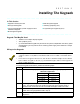
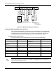
KEYPADS
BLACK
RED
GREEN
YELLOW
CONTROL
TERMINALS
6
7
8
9
Figure 5-1: Keypad Connections to Control Panel.
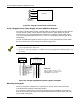
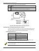
Using a Supplementary Power Supply to Power Additional Keypads
The control provides 750mA auxiliary standby power for powering keypads and other devices
from the auxiliary power output. When the control’s auxiliary power load for all devices
exceeds 750mA, you can power additional keypads from a regulated, 12VDC power supply
(e.g., Alarm-Saf Model AS/PS5-BFS-12-UL). Use a UL Listed, battery-backed supply for UL
installations.
Connect the additional keypads as shown in Figure 5-2, using the keypad wire colors shown.
Be sure to observe the current ratings for the power supply used.
1.
Make connections directly to the screw terminals as shown in
Figure 5-2
. Make no connection
to the keypad blue wire (if present).
2.
Be sure to connect the negative (–) terminal on the power supply unit to terminal 7 (AUX
–
) on
the control.
SUPPLEMENTARY
POWER SUPPLY
+
–
CONTROL
TERMINAL STRIP
AUX AUX.DATA DATA
+ – IN OUT
6789
IMPORTANT:
MAKE THESE
CONNECTIONS
DIRECTLY TO
SCREW
TERMINALS AS
SHOWN.
TO KEYPAD RED WIRE
TO KEYPAD BLK WIRE
TO KEYPAD YEL WIRE
TO KEYPAD GRN WIRE
TO KEYPAD RED WIRE
TO KEYPAD YEL WIRE
IMPORTANT:
Make connections directly to screw
terminals. Make no connection to the
keypad blue wire (if present).
TO KEYPAD BLK WIRE
TO KEYPAD GRN WIRE
Figure 5-2: Using A Supplementary Power Supply For Keypads
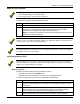
Mounting the Keypads
Mount the keypads at a height that is convenient for the user. Refer to the instructions
provided with the keypad for mounting procedure.
You can either surface-mount or flush-mount keypads (using the 6139TRK Trim Ring Kit).
Refer to the mounting instructions and template included with the keypad and/or trim ring
kit for specific information.