CyberTablet M17 17” Tablet Monitor USERʹS GUIDE
Safe Handling Markings and Symbols Various markings and symbols are used in this user’s guide and on this product, to ensure the safe and correct use of this product and to prevent personal injury and property damage. These symbols and their meanings are as explained below. Understand the information well before reading the body of the user’s guide. WARNING This symbol indicates the presence of potential dangers that, if ignored or applied incorrectly, could lead to death or serious injury.
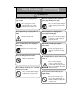
Safety Precautions Always comply with them WARNINGS Securely insert the power plug into the power outlet. If it is not plugged in securely, overheating will occur, possibly resulting in electric shock or fire. Do not plug in the power plug with a wet hand. Electric shock will result. Before cleaning this product, unplug the power plug. Electric shock sometimes results. Before moving this product, detach the power plug and the power cable.
Safety Precautions Always comply with them WARNINGS Do not use a power cable other than the accessory power cable. If a power cable other than the accessory power cable is used, fire or electric shock might result. Unplug the power plug if you do not plan on using the product for an extended period of time. Failure to do so could result in a fire. Do not open or alter the cabinet of this product. The cabinet contains high-voltage areas, so electric shock or other injury will result.
Safety Precautions Always comply with them WARNINGS In the following cases, unplug the product from the AC Adaptor outlet and ask the technical support of Hitachi Software. a.! b. c. d. e. f. After the power cord or AC Adaptor plug is damaged. After a liquid is spilled onto the main unit. After the main unit is exposed to rain or water. After this product malfunctions, even when operated according to the instruction manual. Adjust this product within the ranges specified in the instruction manual.
Contents 1. Introduction ................................................................................................. 1-1 1.1 Product Introduction ........................................................................................... 1-1 1.2 Package Overview .............................................................................................. 1-2 1.3 Part Names and Functions .................................................................................. 1-3 1.3.1 Front Screen .........
Introduction 1. Introduction 1.1 Product Introduction About the Product This 17” flat panel screen with an active matrix, thin-film transistor (TFT), liquid crystal display (LCD).
Introduction 1.2 Package Overview After unpacking, make sure that all of the following parts are included. Parts No. Name Qty.
Introduction 1.3 Part Names and Functions 1.3.1 Front Screen (1) LCD and tablet operating area Receives text and graphical information entered with the stylus pen, and transmits the data to a PC. (4) Front switch panel These switches are used to turn the power ON/OFF, enter OSD menu settings, and adjust the volume. (2) Stand (bottom of body and back) The stand serves to hold the CYBERTABLET M17 in place. The LCD angle can be adjusted in the range of approx. 20° to 70°.
Introduction 1.3.2 Front Panel Controls ! ! ! ! (4) (3) (6) (5) (2) (1) (1) Power button This button turns the CYBERTABLET M17 LCD monitor ON/OFF. (4) Menu button This button is used to display the OSD menu. Press it after making menu selections to apply those. (2) Power indicator his indicator turns green when power is supplied normally to the CYBERTABLET M17 and an image signal is detected. It turns red when no image signal is output from the PC, or when power saving mode is on.
Introduction 1.3.3 Connector Ports Top Bottom (5) (4) (1) ! (2) (3) (4) (5) View of CYBERTABLET M17 Back (1) Power port The AC adapter is connected here. (2) VGA input port This port is used to connect a PC via RGB cable to display images from the PC. (4) Audio input port This port is used to output PC audio from the speakers. The supplied audio cable is connected to this port. ! (5) USB port A USB cable is connected here.
Introduction 1.4 Assembly and Setup Keep the following points in mind when installing the CYBERTABLET M17 Select a stable, flat location. Avoid installing in locations that are dusty, extremely hot, cold, or humid. Also avoid installing in locations exposed to direct sunlight. 1.4.1 Adjusting the Stand Follow the procedure shown below to adjust the stand. (1) Pull up the stand lever. Stand Lever (2) Slide the stand to the desired angle, and release the lever.
Introduction CAUTION Hold the body firmly and slide the stand slowly when adjusting it. When adjusting the stand, if you pull up the lever without holding onto the body, the body may move suddenly, resulting in unexpected injuries or damage to the body. Use the screen at an easily viewable angle. Use the screen at an easily viewable angle, taking into account external light and ceiling lighting, which may reflect off the screen. 1.4.
Introduction 1.4.3 Connection Procedure Follow the procedure below to connect the PC and CYBERTABLET M17 PC ! ! (2) ! ! ! ! ! ! (3) (1) (4) (5) (6) To power outlet (1) Connect the RGB cable to the VGA input port on the side of the CYBERTABLET M17, and tighten the screws to fasten. Connect the other end of the cable to the PC VGA port, and tighten the screws to fasten. (2) Connect the USB cable to the USB port on the side of the CYBERTABLET M17.
Introduction WARNING Use the AC Adaptor supplied with this product. Use only AC Adaptor or power cables specified by the manufacturer. Use of improper adaptors or cables can damage the product or cause a fire. Using this product with Windows 98 and Windows 98 Second Edition When using this product with Windows 98 or Windows 98 Second Edition, on some computers it may be necessary to install a driver for the USB controller located inside the PC.
Usage 2. Usage Procedures This section describes the basic procedures for using CYBERTABLET M17. For information on using advanced CYBERTABLET M17 features, see the CYBERTABLET M17 Software and User's Guide. 2.1 Turning the CYBERTABLET M17 On This section describes how to turn the CYBERTABLET M17 on. (1) Turn on the CYBERTABLET M17 power. Push the power button (2) Turn on the PC and allow Windows to start. (3) The CYBERTABLET M17 Software starts automatically.
Usage 2.2 Using the Stylus Pen This section describes how to use the CYBERTABLET M17 stylus pen. 2.2.1 How to Use the Stylus Pen The stylus pen has a power switch. Battery life can be prolonged by ON/OFF the power switch. To draw characters and figures using the stylus pen, set the power switch of the stylus pen to the ON position. ON/OFF switch Push the switch ON OFF 2.2.2 Basic Stylus Pen Operations The stylus pen can be used in the same way as a mouse.
Usage 2.2.3 Stylus Pen Settings The stylus pen has one pen tip button, and two side buttons. Mouse actions can be assigned to these three buttons. The default button settings are summarized in the following table. Button User action Corresponding mouse action Pen tip Press the pen tip against the display. Mouse left-click Side Button No. 0 Press the button with the pen tip slightly removed from the screen (5 mm or less). Mouse left double-click Side Button No. 1 Same as above.
Usage 2.2.4 Changing the Battery in the Stylus Pen The stylus pen contains a single AAA alkaline dry cell. If the pen begins to operate erratically (e.g., if pen input is cut off), change the battery as described below. Note that battery life is approximately 1,800 hours under normal usage. If the residual quantity of a battery decreases, the center of a side button will light up red. If the center of a side button will light up red, change the battery as described below.
Usage 2.2.5 Replacing the Stylus Pen Tip When the stylus pen tip wears down and becomes too short, replace it as described below. (1) Using the special pin set, remove the stylus pen tip. (2) Insert a new pen tip into the stylus pen.
Usage 2.3 Using the OSD Menu The OSD menu is used when adjusting the CYBERTABLET M17 LCD screen. OSD is an abbreviation for On-Screen Display. The OSD feature allows you to view and adjust the settings for the display on the screen. •(+) button 2.3.1 OSD Buttons and Their Functions 1.Increase the brightness of the display image. •Menu button 2.Increase value of the adjustment To display the OSD menu. item. •AUTO/SELECT button • (-) button 1.To select the adjustment items 1.
Usage 2.3.2 OSD Adjustment Options (1) BRIGHTNESS Used to adjust screen brightness. (0-100) (2) CONTRAST Used to adjust color contrast. The larger the value, the brighter the image will be. (0-100) (3) LCD ADJUSTMENT CLOCK PHASE H.POSITION V.POSITION RETURN : Used to adjust screen size. (0-100) : Used to adjust the sampling timing (phase) for converting the analog input signal to a digital input signal. (0-63) : Used to change the horizontal position of the screen.
Usage (4) COLOR TEMPRATURE Used to adjust the color temperature of the screen. (SRGB, 9300K, 7200K, 6500K, 5000K) USER : Used to adjust the red, green, and blue colors of the screen. (0-100) RETURN : Used to return to the previous page. (5) ECO MODE Used to turn the ECO mode ON, and limit brightness setting from 0 to 20 to reduce power consumption. RETURN : Used to return to the previous page. (6) LANGUAGE Used to select the display language.
Usage (7) OTHER SETUP SMOOTH : Used to adjust the smoothness of the image. (0-3) OSD H.POSITION : Used to adjust horizontal position of OSD window. (0-100) OSD V.POSITION : Used to adjust vertical position of OSD window. (0-100) OSD TRANSPARENCY : Used to turn OSD window background transparency ! ! ON/OFF. OSD TIMEOUT VOLUME MODE MESSAGE : Used to set the amount of time before the OSD menu closes automatically. (0-60) : Used to adjust the speaker volume.
Appendix 3. Appendix 3.1 Troubleshooting First, check adjustments and handling methods and check for poor cable connections. Those are often the causes of problems when nothing is actually broken. Screen display-related problems In this case PC screen does not display on CYBERTABLET M17. Check this Is the PC power on? And do this For Solution, please refer to the PC PC manual and other documentation.
Appendix In this case Stylus pen tip and pen cursor positions do not match. Check this Is pen tip worn down? And do this Check if the pen tip is worn down or is too short. (For details on how to replace the stylus pen tip, see “2.2.5 Replacing the Stylus Pen Tip” on page 2-5 of this User’s Guide.) Are there any electronic This product is susceptible to devices located nearby the electromagnetic noise, so use the CYBERTABLET M17 such CYBERTABLET M17 away from as microwave ovens or devices that emit noise.
Appendix 3.2 System Specifications Item Product name Specification CYBERTABLET M17 Tablet Monitor Display Driver type Active-Matrix Liquid Crystal Display (TFT) characteristics Effective screen size 731.8 mm 337.920 mm (W)×270.336 mm (H) 17 in. 13.3 in (W) x 10.7 in. (H) Resolution 1280×1024 (SXGA) Pixel pitch 0.264×0.