Installation and Operating Guide FastStor
Copyright Notice © Copyright ADIC 1997, 1998, 1999 The information contained in this document is subject to change without notice. This document contains proprietary information which is protected by copyright. All rights are reserved. No part of this document may be photocopied, reproduced, or translated to another language without the prior written consent of ADIC.
Copyright Notice (Europe) © Copyright 1997 ADIC Europe All rights reserved. No part of this document may be copied or reproduced in any form or by any means, without prior written permission of ADIC Europe, ZAC des Basses Auges, 1, rue Alfred de Vigny, 78112 – Fourqueux, FRANCE. ADIC Europe assumes no responsibility for any errors that may appear in this document, and retains the right to make changes to these specifications and descriptions at any time, without notice.
Regulatory Notices FCC Notices (USA Only) This equipment generates, uses, and can radiate radio frequency energy and, if not installed and used in accordance with the manufacturer’s instruction manual, may cause interference with radio and television reception. This equipment has been tested and found to comply with the limits for a Class B digital device, pursuant to Part 15 of the FCC Rules.
EN 55022 Compliance (Czech Republic Only) This device belongs to category B devices as described in EN 55022, unless it is specifically stated that it is a category A device on the specification label. The following applies to devices in category A of EN 55022 (radius of protection up to 30 meters). The user of the device is obliged to take all steps necessary to remove sources of interference to telecommunication or other devices.
DECLARATION OF CONFORMITY according to EN 45014 Manufacturer’s Name: Advanced Digital Information Corporation Manufacturer’s Address: 11431 Willows Road Redmond, Washington 98052 USA ZAC des Basses Auges 1, rue Alfred de Vigny 78112 Fourqueux, FRANCE declares, that the product: Product (Produit, Erzeugnis): FastStor Model Numbers (Marque Commercial, Warenbezeichnung): FastStor FS-DLT 4000 FastStor FS-DLT 7000 FastStor FS-DLT 8000 conforms to the following international standards, Emissions: EN 500
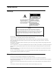
Safety Notices Warnings CAUTION RISK OF ELECTRIC SHOCK DO NOT OPEN This symbol should alert the user to the presence of "dangerous voltage" inside the product that might cause harm or electric shock. CAUTION : TO REDUCE THE RISK OF ELECTRIC SHOCK, DO NOT REMOVE COVER (OR BACK). NO USER-SERVICEABLE PARTS INSIDE. REFER SERVICING TO QUALIFIED SERVICE PERSONNEL. Caution All safety and operating instructions should be read before this product is operated, and should be retained for future reference.
Blank Page viii Safety Notices
Table of Contents Copyright Notice .................................................................................................................................................................................. ii Copyright Notice (Europe) ..................................................................................................................................................................iii Regulatory Notices ....................................................................................
Disabling AUTOCLEAN.................................................................................................................................................... 43 LOAD FIRMWARE................................................................................................................................................................... 44 DISPLAY COUNTS...................................................................................................................................................
Quick Start Guide This Guide … ❐ provides a quick guide for experts who are familiar with installing hardware and software.
Follow these steps to quickly get started using your ADIC FastStor: Notes The following defaults have been set at the factory, and in most cases, should not have to be changed. LDR SCSI ID: 1, DRV SCSI ID: 3 FastStor DLT 4000 Tape Density: 40GB FastStor DLT 7000 Tape Density: 70GB FastStor DLT8000 Tape Density: 80GB Operating Mode: Random Logon String: FastStor SCSI Terminator AC Line Cord xii 1. Install AC line cord, first to FastStor, then to AC outlet. 2. Install SCSI terminator on FastStor.
3. Power up your FastStor by pressing the Power button. Power Button 4. Install data cartridges in slots 1 through 5 of your FastStor. LCD indicates 1-5 are loaded.
5. Using the Mode Menu, move the cartridge from slot 1 to slot 6, and from slot 2 to slot 7. Press MODE button until LOAD SLOT is displayed. Press SELECT button twice. Tape in slot 1 will move to slot 6. Repeat above steps to move tape in slot 2 to slot 7. 6. Install additional data cartridges in slots 1 and 2. LCD indicates 1-7 loaded.
7. Connect SCSI cable to rear of FastStor and to SCSI adapter on your host computer. SCSI Cable 8. Power up your host computer. 9. Verify your backup software. Your ADIC FastStor is ready for operation.
Blank Page xvi Quick Start Guide
Chapter Introduction This Chapter … ❐ provides a physical description of the switches, indicators and connectors on the front and rear panels of the external FastStor ❐ describes the drive and media used in the FastStor ❐ describes other requirements (additional hardware and/or software) needed to utilize the FastStor ❐ provides a brief overview of the FastStor features.
W elcome to your ADIC FastStor (shown above). Your FastStor is a fully automated, high-performance, highcapacity, mass storage system. The FastStor is designed to provide you with unattended, near-line and off-line data storage, archiving, backup, hierarchical storage management (HSM), and retrieval for low- and mid-range servers and networks. Through the remainder of this manual, references will be made to the FastStor.
Features ❐ Multi-function Operator Panel. The Operator Panel, located to the right, under the front door, employs a 1-line by 10character liquid crystal display (LCD), a four-key keypad, and three LEDs to permit you to monitor and control the operations of your library.
DLT Drives Your ADIC FastStor is equipped with a third-, or fourth-generation DLT drive. The DLT4000 and DLT7000 drives can read and write 2.6 GB, 6.0 GB, and 10.0 GB tape formats for 100% interchange compatibility with earlier DLT drives. The DLT 8000 drive can read and write 10.0, 15.0, 20.0, and 35.0 GB tape formats for 100% interchange compatibility with the DLT 2000, DLT 2000xt, DLT 4000, and DLT 7000 drives.
Switches and Indicators The following figures shows the switches and indicators located on the front and rear panels of the FastStor. FastStor Series Rear Panel AC Power Connector Receptacle for AC power cord. SCSI Channel Connectors Connections for the interface cable that connect the unit with the host computer and/or to other devices on the SCSI channel (including additional FastStor units). The interface cable can be attached to either connector.
FastStor Series Front Panel Power LED (green) Activity LED (blinking amber) Alarm LED (red) LCD 6 Introduction Indicators Illuminates when power is on. Indicates robotic and drive activity. A slow blinking interval indicates FastStor robotic activity and a fast interval indicates drive activity. Illuminates whenever an error has occurred. 1-line by 10-character Liquid Crystal Display. Displays information about drive status, operational messages, and error messages.
The following illustration shows the layout of the LCD. The normal on-line message (LdR REAdY) is displayed on the top line. On-line, off-line, and error messages appear on this line. DC indicates that data compression is selected on the drive. WP indicates that a write-protected data cartridge is loaded into the drive. CT indicates that the drive head needs to be cleaned. The large numeric field in the center of the display normally indicates which cartridge is loaded into the drive.
FastStor Series Operator Panel Keypad 8 MODE Press this button to enter or exit off-line mode menus. NEXT Selects next item or value in the currently displayed menu. SELECT Causes the FastStor to execute the current menu (displayed on line 1 of the LCD). PREVIOUS Selects previous item or value in the currently displayed menu. POWER Press and release this button to turn on your FastStor. Press and hold this button for 2 seconds to turn off your FastStor.
DLT Media The data cartridges used in the DLT drive are housed in 4-inch plastic cases and employ ½-inch metal particle tape. BAR CODE LABEL ORANGE INDICATOR WRITE-PROTECT SWITCH WRITE-PROTECTED WRITE-ENABLED DLT Data Cartridge The write-protect switch is used to prevent recording over existing data. To prevent recording or deleting, place the write-protect switch to the open position. The drive senses the position of the switch and will not allow writing in this position.
Other Requirements SCSI Host Adapter Your FastStor must be connected to either an integrated SCSI host or a separate SCSI interface (host adapter) card installed in the computer – either directly to the I/O connector on the card or as part of an existing SCSI chain. The host adapter you choose will depend on your system requirements and your needs. If you are not sure about your host adapter requirements, please call ADIC’s Technical Assistance Center (ATAC) and ask for assistance.
Chapter Hardware Installation This Chapter. . .
For the most part, installation is simply a matter of checking all necessary SCSI connections, installing the application software (backup or otherwise) on the host computer, and applying power. The FastStor defaults set at the factory should be sufficient for most applications. Unpacking and Inspecting Caution If the operating environment differs from the storage environment by 15° C (30° F) or more, let the unit acclimate to the surrounding environment for at least 12 hours.
Installing the SCSI Cable and Terminator Notes Make sure that the interface cable you are planning on using has the appropriate connectors on each end. The FastStor employs a 68-pin high-density SCSI connector on the rear panel. If your host computer’s SCSI connector is different from that on the FastStor, you will need to obtain an adapter or a different cable. Consult your dealer or ATAC if you need help. The interface cable must be shielded – ADIC can supply you with the correct type.
Connecting More than One FastStor If you are connecting more than one FastStor on the same SCSI channel, simply connect each unit to the previous unit with an additional shielded interface cable. It does not matter which SCSI connector on each FastStor you connect the interface cable to. Make sure that you configure each FastStor unit with a unique drive SCSI ID and loader ID. Your FastStors will not function properly if they have the same SCSI IDs.
Chapter Operation and Maintenance This Chapter. . .
Normal Operations General Guidelines Once your FastStor and your choice of application software are installed and configured, you can automatically perform backup and restore operations through the application software. You do not need to intervene unless you need to replace cartridges. Always follow these general operating guidelines: ❐ Do not open the front door of the FastStor unless you must perform manual Mode commands, or change media.
While the FastStor initializes, the LCD will appear as shown below. The Activity LED will blink slowly, and the Activity Bars will appear on the LCD. L r init At the completion of FastStor initialization, the drive will initialize and the LCD will appear as shown below. The Activity LED will blink fast, and the Activity Bars will appear on the LCD.
Your FastStor consists of two SCSI devices; the drive and the robotics. Depending upon your requirements, you may need to change the SCSI ID default settings for your installation. To change the SCSI ID of the robotics and/or the drive, perform the following steps: ❐ Repeatedly press the MODE button on the Operator’s Panel until SET SCSI (Mode 6) appears on the first line of the LCD. ❐ Press the SELECT button. LdR SCSI will now appear on the LCD. ❐ Press the SELECT button to select the robotics.
Prepare and Install the Data Cartridges ❐ If necessary, unlock and open the front door to access the cartridge storage slots. ❐ Make sure that the write-protect switch is set appropriately on each cartridge. Slide the switch to the appropriate position by pushing it with your finger. ORANGE INDICATOR WRITE-PROTECT SWITCH WRITE-PROTECTED WRITE-ENABLED DLT Cartridge Write-Protect Switch Storage slot 6 and 7 are loaded from slots 1 and 2 respectively, using the Operator’s Panel.
❐ Install five additional cartridges into storage slots 1 through 5. ✔ Verify that the LCD now shows that slots 1 through 7 have tapes present. Close and Lock the Front Door Close the FastStor door, turn the key a quarter-turn clockwise and remove it from the lock. ❐ Turn on the host computer power and launch the software application. The application will now control the FastStor. Use the Mode commands, described on the following pages, to manually perform FastStor functions.
FastStor Modes The following diagram is a quick reference guide to the Modes described on the next few pages. Mode 1A (When drive empty) LOAD DRV SRC SLOT N Mode 1B (When tape in drive) EJECT DRV DST SLOT N Mode 2 LOAD SLOT SRC SLOT n Mode 3 EJECT SLOT SRC SLOT N Mode 4 EJECT PCKR DST SLOT N Mode 5 DENSITY FMT 2_6 FMT 6 FMT 10 FMT 10C FMT 15.
❐ To access any of the Modes, press the MODE button repeatedly until the LCD displays the desired mode on line 1. Notes It is only possible to scroll forward through the Mode choices. If you pass the mode you desire, continue to press the MODE button until the mode you desire is again displayed on the LCD. While accessing Modes 1-6, the FastStor is not available to your software application. ❐ To exit any of the Modes and return to LdR REAdY, press the MODE button.
❐ Use the NEXT or PREVIOUS button to scroll through the slot choices. Press SELECT when the slot you wish to load is displayed. L r rea y 2 3 4 5 6 7 Your FastStor will load the desired tape into the drive. After completing the task, the FastStor will return to LdR REAdY, and the slot number of the tape in the drive will be displayed in the center of the LCD. Mode 1B – EJECT DRV Mode 1B causes the FastStor to eject the tape from the drive and place it into the storage slot that it was loaded from.
When your FastStor has completed the command, it will return to LdR REAdY. L r rea y 1 2 3 4 5 6 7 Mode 2 – LOAD SLOT Mode 2 causes the FastStor to load slot 6 from slot 1, or slot 7 from slot 2. Note If slots 6 and 7 already have cartridges, Mode 2 is not selectable on the LCD. ❐ Place a cartridge in slot 1 if loading slot 6, slot 2 if loading slot 7, or both if loading slots 6 and 7.
Mode 3 – EJECT SLOT Mode 3 causes the FastStor to move a tape from slot 6 to slot 1, or from slot 7 to slot 2. Note If the source slot is empty, or the destination slot is full, selecting EJECT SLOT will cause a blinking RESELECT to appear on the LCD. The blinking RESELECT indicates that you attempted to select an invalid mode. ❐ To access Mode 3, press the MODE button until the LCD appears as shown: eject slot 2 ❐ 3 4 5 6 7 Press the SELECT button to select Mode 3.
Mode 4 – EJECT PCKR Mode 4 causes the FastStor to eject a tape left in the Media Picker at power down to any empty destination slot. Notes A tape will normally not be left in the Picker at power down. Executing EJECT PCKR Mode when the Media Picker does not have a tape will result in PCKR EMPTY and a large E (indicating an error condition) appearing on the LCD for approximately 25 seconds. If this occurs, you may press the Mode button to return the FastStor the LdR REAdY before the 25 seconds elapses.
Mode 5 – DENSITY Mode 5 is used to set the density format of the data cartridge tape. All previously unformatted DLTtape III, DLTtape IIIXT, and DLTtape IV data cartridges can be formatted to the densities shown in the following table. Drive Model Data Cartridge Cartridge Density (native mode) Cartridge Density (compressed mode) DLT 4000 DLTtape III DLTtape IIIXT DLTtape IV 2.6, 6.0, 10.0 GB 15.0 GB 20.0 GB 20.0 GB 30.0 GB 40.0 GB DLT 7000 DLTtape III DLTtape IIIXT DLTtape IV 2.6, 6.0, 10.0 GB 15.
Notes Attempting to select Mode 5 when the drive is empty will result in a NO TAPE error message appearing on the LCD. Press MODE to return the FastStor to LdR REAdY. If a NOT LOAdEd error message appears on the LCD when pressing SELECT, the current tape has not completed loading. Press MODE to clear the error and return the FastStor to LdR REAdY. If a CANNOT FMT error message appears on the LCD when pressing SELECT, the drive cannot reformat the cartridge (i.e., TK85 cartridge in a DLT4000 drive).
❐ Press SELECT to choose the FastStor robotics. The LCD will appear as shown (X is the current ID of the robotics.): L rI x 2 ❐ 3 4 5 6 7 Press NEXT or PREVIOUS button to scroll through the ID choices. Press SELECT when the desired ID is displayed. The LCD will appear as shown: rv scsi 2 ❐ 3 4 5 6 7 Press SELECT to choose the drive. The LCD will appear as shown (X is the current SCSI ID of the drive.
Normal Maintenance Cleaning the Drive Head Keeping a drive clean is the single most important requirement for achieving and maintaining superior performance. Cleaning the head should always be performed as the first step if the CT field appears on the LCD. The tape head may be cleaned once a month, or when the CT field appears on the Operator’s Panel LCD. Some application packages feature an auto clean cycle. If your application supports an auto clean function, ADIC strongly recommends that you use it.
The following table tells you when to use the cleaning tape: If . . . 1. The CT field appears on the Operator’s Panel LCD It means . . . You should . . . The drive head needs cleaning or the tape is bad Use the cleaning tape to clean the drive head. When cleaning is complete, log the cleaning onto the label. 2. The data cartridge may be damaged A data cartridge causes the CT field to appear on the Operator’s Panel LCD 3.
Cleaning the Enclosure The outside of the enclosure can be cleaned with a damp towel. If you use a liquid all-purpose cleaner, apply it to the towel. Do not directly spray the enclosure.
Chapter Troubleshooting and Diagnostics This Chapter … ❐ contains some general suggestions to aid you in solving problems – should you ever run into them. ❐ includes information on error codes and the built-in diagnostics.
Installation Problems Usually, problems encountered during the installation of your FastStor are caused by improper SCSI bus configuration, application software configuration errors or by an OS that has not been correctly configured.
iag menu 2 3 4 5 6 7 The following functions are available under the dIAG MENU: dSP FW When executed, this function displays the revision of the operating firmware used by FastStor microprocessors and the drive. SIGN ON Use this function if your application software does not support FastStor, but does support the SCALAR library. CHG MOdE Use this function to change the Mode of Operation from/to RANDOM or SEQUENTIAL.
2 ❐ 3 4 5 6 7 Press the SELECT button to display the firmware revision for the FastStor. The LCD will appear as shown (NNNN is the revision number of the firmware.): l fw NNNN 2 ❐ 3 4 5 6 7 Press NEXT to access the dSP dRV FW sub-function. The LCD will appear as shown: sp rv fw 2 ❐ 3 4 5 6 7 Press the SELECT button to display the firmware revision for the drive. The LCD will appear as shown (NNNN is the revision number of the firmware.
❐ Press NEXT to access the dSP MTN FW sub-function. The LCD will appear as shown: sp mtn fw 2 ❐ 3 4 5 6 7 Press the SELECT button to display the firmware revision for the Motion firmware. The LCD will appear as shown (NN is the revision number of the firmware.): mtn fw NN 2 ❐ 3 4 5 6 7 Press NEXT to access the dSP FP FW sub-function. The LCD will appear as shown: sp fp fw 2 ❐ 3 4 5 6 7 Press the SELECT button to display the firmware revision for the front panel firmware.
❐ Press NEXT to access the dSP bT FW sub-function. The LCD will appear as shown: sp T fw 2 ❐ 3 4 5 6 7 Press SELECT to display the firmware revision for the boot firmware. The LCD will appear as shown (NNNN is the revision number of the frimware.): t fw NNNN 2 ❐ 3 4 5 6 7 Press SELECT to return the FastStor to LdR REAdY.
continue this process until the volume is full. It is important to note that while in Sequential-Access mode, the FastStor robotics is not logically connected to the SCSI bus and does not respond to SCSI commands. ❐ After entering the dIAG MENU, press the MODE button until CHG MOdE appears on the LCD: Chg mo e 2 3 4 5 6 7 ❐ Press the SELECT button to display the current mode. ❐ Press the NEXT or PREVIOUS button to toggle the mode between SEQUENTIAL and RANDOM. ❐ Press the SELECT button.
❐ After entering the dIAG MENU, press the MODE button until CYCLE TEST appears on the LCD: Cycle TEST 1 ❐ 2 3 4 5 6 7 Press SELECT to initiate the CYCLE TEST function. The following will appear on the LCD: CycleS 1 2 3 4 5 6 ❐ Press the NEXT button to cycle through the number of desired cycles. ❐ Press SELECT when the desired number of cycle tests is displayed. 7 Notes If you want the FastStor to execute CYCLE TEST continually, press PREVIOUS until CYCLES 0 is displayed.
❐ Press the SELECT button to begin the drive head cleaning process. The LCD will display the following blinking message: Ct 2 (Sel) 2 ❐ 3 4 5 6 7 If necessary, place a cleaning tape in slot 2 then press SELECT. FastStor will move the cleaning tape to the drive and cleaning will begin. During cleaning the following message will be displayed on the LCD, and the Activity Bars will indicate the drive activity.
AUTOCLEAN The AUTOCLEAN function is for use with application software that does not support automated cleaning of the drive head. Applications that support automated cleaning manage tape location and use, including that of the cleaning cartridge. Do not use the AUTOCLEAN function if your application software supports automated cleaning cycles. Enabling AUTOCLEAN Note The default condition is AUTOCLEAN Off.
Notes If, when you press SELECT, slot 7 is full, FastStor will return a dEST FULL error message and AUTOCLEAN will not be enabled. In this instance, use the UNLOAD SLOT mode to empty slot 7 first, then enable AUTOCLEAN. If you wish to abort while enabling the AUTOCLEAN function, before placing the cleaning cartridge in slot 2 and pressing SELECT, press the MODE button. FastStor will return to LdR REAdY and AUTOCLEAN will not be enabled.
2 ❐ 3 4 5 6 7 Press the SELECT button to access the AUTOCLEAN function. The following message will be displayed on the LCD: AC OFF 3 ❐ 4 5 6 7 Press the SELECT button to disable the AUTOCLEAN function. FastStor will move the cleaning cartridge from slot 7 to slot 2. The following blinking message will be displayed on the LCD: RMV 2 (SEL) 2 ❐ 3 4 5 6 Remove the cleaning cartridge from slot 2, then press SELECT. FastStor will return to LdR REAdY.
2 ❐ 3 4 5 6 7 Press the SELECT button to access the first event.
❐ Press SELECT again to return the number of times that FastStor has picked a cartridge from any of the front slots. The display will appear similar to the following: (000000XX) 2 ❐ 3 4 5 6 7 Press NEXT to access the next event.
❐ If not already installed, place a FUP tape in slot 2 then press SELECT. If you press SELECT before placing the FUP tape in slot 2, UPG dRV FW will appear momentarily on the LCD and then the blinking CT 2 (SEL) message will reappear. The drive will be placed in a “prepare for firmware upgrade via tape” mode. The FastStor will move the FUP tape to the drive and the upgrade process will begin.
FastStor Error Messages If, during operation of your FastStor an error occurs, the FastStor will halt the current operation and an error message will be displayed on the LCD. In all cases, after removing the cause of the problem, cycle power on your FastStor and try the last operation again.
Environmental Considerations For best performance of your FastStor, and to minimize the chance of condensation, please observe the following guidelines: ❐ Install your FastStor on a level surface. Do not place FastStor on a carpeted surface. ❐ If you expose cartridges to temperatures outside the operating limits, 10-40°C (50-104°F), stabilize them by leaving the cartridges in the operating temperature for a minimum of two hours before you use them.
Blank Page 50 Troubleshooting and Diagnostics
Appendix Specifications This Appendix … ❐ contains specification information on the FastStor and the DLT drive.
Drive: Type: FastStor DLT 4000 — Quantum® model DLT4000 FastStor DLT 7000 — Quantum® model DLT7000 FastStor DLT 8000 — Quantum® model DLT8000 Data Capacity: (compressed mode) Up to 40 GB per 1800 ft cartridge (DLT4000) Up to 70 GB per 1800 ft cartridge (DLT7000) Up to 80 GB per 1800 ft cartridge (DLT8000) Data Transfer Rate: (compressed mode) 3.0 MB/sec. sustained (180 MB/min., DLT4000) 10.0 MB/sec. sustained (600 MB/min., DLT7000) 12.0 MB/sec. Sustained (720 MB/min.